ANTI-LOCK BRAKES
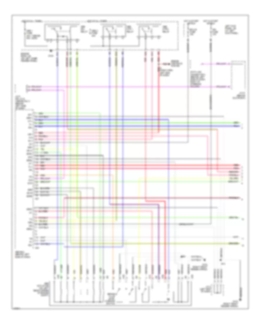
Anti-lock Brake Wiring Diagrams, with VSC (1 of 3) for Toyota Land Cruiser 2000
 https://portal-diagnostov.com/license.html
Automotive Electricians Portal FZCO
Automotive Electricians Portal FZCO
https://portal-diagnostov.com/license.html
https://portal-diagnostov.com/license.html
Automotive Electricians Portal FZCO
Automotive Electricians Portal FZCO
List of elements for Anti-lock Brake Wiring Diagrams, with VSC (1 of 3) for Toyota Land Cruiser 2000:
- (engine harn, left rear corner of engine compt) e14
- A37
- A38
- A39
- A40
- A41
- A44
- Abs & ba & trac & vsc actuator
- Abs & ba & trac & vsc ecu (behind left side of dash)
- Abs 1 fuse 50a
- Abs 2 fuse 40a
- Abs mtr 1 relay
- Abs mtr 2 relay
- Abs sol relay
- Ast
- B10
- B11
- B12
- B14
- Braided
- E8 (engine harn, center rear of engine compt)
- Engine controls system
- Engine room j/b (on left inner fender panel)
- Fl+
- Fl-
- Fr+
- Fr-
- Fss
- G103 (right front fender apron)
- Gnd1
- Gnd2
- Hot at all times
- Hot in run or start
- I2 (dash harn, left end of dash)
- Ig2
- Ign fuse 10a
- Left kick panel j/b (at left kick panel)
- Mr1
- Mr2
- Mss
- Mt+
- Mt-
- Mtt
- P10
- Pmc
- Pnk
- R1+
- R2+
- Red
- Sa1
- Sa2
- Sa3
- Sflh
- Sflr
- Sfrh
- Sfrr
- Srlh
- Srlr
- Srrh
- Srrr
- Str
- Vcm
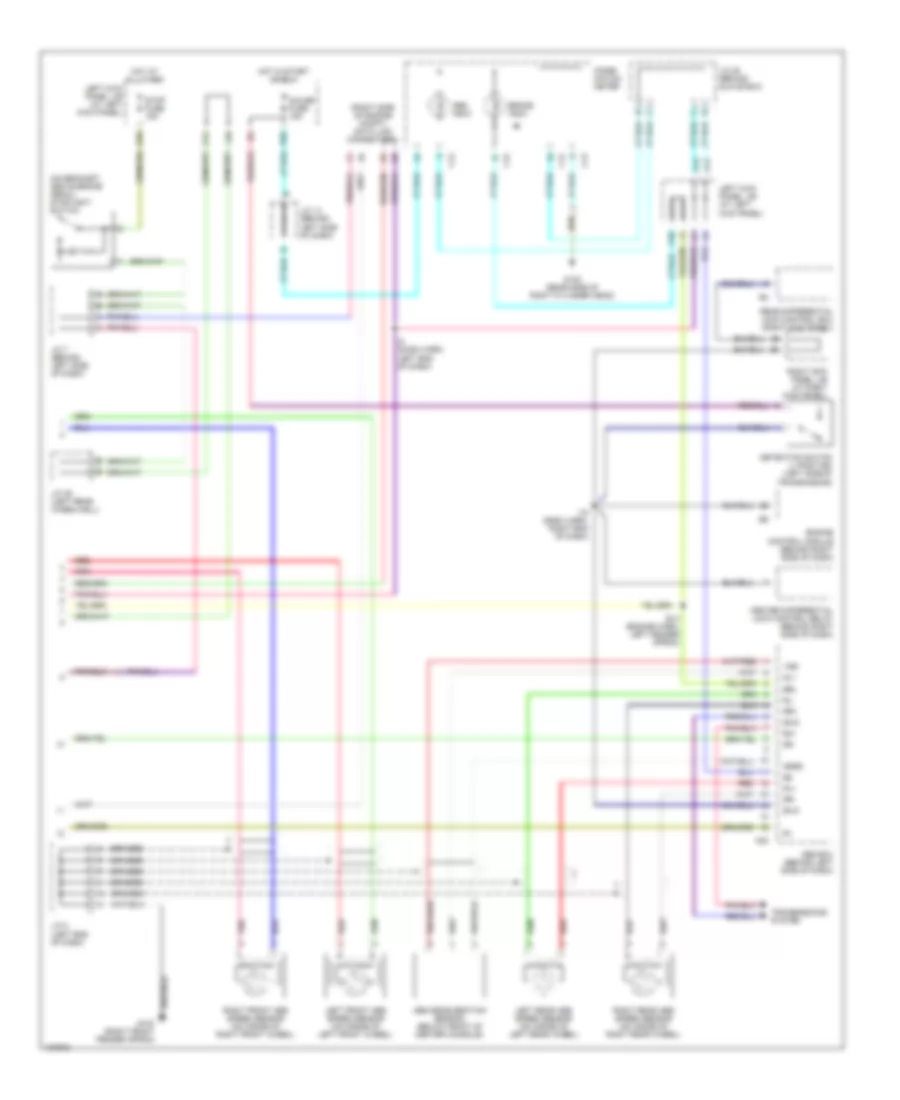
Anti-lock Brake Wiring Diagrams, with VSC (2 of 3) for Toyota Land Cruiser 2000
List of elements for Anti-lock Brake Wiring Diagrams, with VSC (2 of 3) for Toyota Land Cruiser 2000:
- B10
- Braided
- Ecu-ig fuse 15a
- Gauge fuse 15a
- Hot at all times
- Hot in run or start
- I34
- J/c 14 (behind upper center of dash)
- J/c 19 (behind upper right side of dash)
- J/c 23 (behind glove box)
- J/c 42 (behind left side of dash)
- Left front abs speed sensor
- Left kick panel j/b (at left kick panel)
- Left rear abs speed sensor
- Master cylinder pressure sensor (on brake master cylinder)
- N15
- O12
- P83
- Park/ neutral position switch (on left side of trans- mission)
- Parking brake switch (on base of park brake lever)
- Pmc
- Pnk
- Red
- Right front abs speed sensor
- Right kick panel j/b (at right kick panel)
- Right rear abs speed sensor
- Stop fuse 15a
- Stoplight switch (on bracket, above brake pedal)
- Vcm
- Vsc warning buzzer (behind left side of dash)
Anti-lock Brake Wiring Diagrams, with VSC (3 of 3) for Toyota Land Cruiser 2000
List of elements for Anti-lock Brake Wiring Diagrams, with VSC (3 of 3) for Toyota Land Cruiser 2000:
- A42
- A43
- Abs & ba & trac & vsc ecu (behind left side of dash)
- Abs deceleration sensor (below rear of center console)
- Abs ind
- Active trac ind
- Braided
- Brake ind
- Brl
- C12
- C14
- C15
- Combination meter
- Computer data lines system
- D/g
- Data link connector 3 (behind left side of dash)
- Eng+
- Eng-
- Engine control module (behind right side of dash)
- Exi
- Exi3
- G103 (right front fender apron)
- G120 (rear side of right cyl head)
- Ggnd
- Gl1
- Gl2
- Gnd3
- Gnd4
- Gss
- Gyaw
- Ig1
- Ind
- Infr
- J/c 16 (behind upper right side of dash)
- J/c 21 (behind upper right side of dash)
- J/c 28 (behind upper right side of dash)
- J/c 42 (behind left side of dash)
- Left kick panel j/b (at left kick panel)
- Neo
- P12
- P41
- P46
- Pkb
- Pnk
- Red
- Rl+
- Rl-
- Rr+
- Rr-
- Rss
- Sil
- Slip ind
- Stp
- Tfn
- Transfer neutral position detection switch (on left side of trans- mission)
- Transmissions system (center diff lock detection sw)
- Transmissions system (transfer l position detection sw)
- Trc+
- Trc-
- Vgs
- Vsc off ind
- Vsc trac ind
- Vscw
- Vys
- Yaw
- Yaw rate sensor (under center of dash, on transmission tunnel)
- Yaw2
- Yss
Anti-lock Brake Wiring Diagrams, without VSC (1 of 2) for Toyota Land Cruiser 2000
List of elements for Anti-lock Brake Wiring Diagrams, without VSC (1 of 2) for Toyota Land Cruiser 2000:
- (1998-99) (2000)
- A10
- A11
- A21
- A23
- Abs 1 fuse 40a 50a
- Abs 2 fuse 40a
- Abs actuator (on left rear corner of engine compt)
- Abs ecu (behind left side of dash)
- Abs mtr 1 relay
- Abs mtr 2 relay
- Abs sol relay
- B10
- B11
- B12
- B14
- Brake fluid level warning switch
- D/g
- D16
- Data link connector 3 (behind left side of dash, right of steering column)
- E14
- Ecu-ig fuse 15a
- Engine controls system
- Engine room j/b (on left inner fender panel)
- Fl+
- Fl-
- Fr+
- Fr-
- G102
- G103 (right front fender apron)
- Grd1
- Grd2
- Grd3
- Grd4
- Hot at all times
- Hot in start or run
- I2 (dash harn, left end of dash)
- Ig1
- Ig2
- Ign fuse 10a
- J/c 2 (left end of dash)
- J/c 21 (behind glove box)
- J/c 9 (or j/c 5) (1998-99 only) (behind left side of dash)
- Left kick panel j/b (at left kick panel)
- Mr1
- Mr2
- Mt+
- Mt-
- Pnk
- R1+
- R2+
- Red
- Sa1
- Sa2
- Sflh
- Sflr
- Sfrh
- Sfrr
- Srh
- Srr
- Stp
Anti-lock Brake Wiring Diagrams, without VSC (2 of 2) for Toyota Land Cruiser 2000
List of elements for Anti-lock Brake Wiring Diagrams, without VSC (2 of 2) for Toyota Land Cruiser 2000:
- (on bracket, above brake pedal) stoplight switch
- (right side of engine compt) data link connector 1
- A22
- Abs deceleration sensor (below front of center console)
- Abs ecu (behind left side of dash)
- Abs indic
- B10
- Braided
- Brake indic
- Brl
- C12
- C13
- C15
- Center differential lock control relay (behind right side of dash)
- Combi- nation meter
- Detection switch (l position) (left side of transmission)
- E14 (engine harn, left fender apron)
- Engine control module (behind right side of dash)
- Exi
- Exi2
- Exi3
- G103 (right front fender apron)
- G120 (rear side of right cylinder head)
- Gauge fuse 15a
- Ggrd
- Gl1
- Hot at all times
- Hot in start or run
- I15 (dash harn, right end of dash)
- I2 (dash harn, left end of dash)
- J/c 14 (behind left side of dash)
- J/c 2 (left end of dash)
- J/c 28 (behind glove box)
- J/c 35 (left rear wheelwell)
- J/c 7 (behind left side of dash)
- J10
- Left front abs speed sensor (on inside of left front wheel)
- Left kick panel j/b (at left kick panel)
- Left rear abs speed sensor (on inside of left rear wheel)
- O12
- P10
- P11
- P12
- P83
- Pnk
- Rear differential lock control ecu (right kick panel)
- Red
- Right front abs speed sensor (on inside of right front wheel)
- Right kick panel j/b (at right kick panel)
- Right rear abs speed sensor (on inside of right rear wheel)
- Rl+
- Rl-
- Rr+
- Rr-
- Stop fuse 15a
- Transmssions system
- Vgs

 Čeština
 Dansk
Dansk Deutsch
 Ελληνικά
 English
 Español
 Suomi
Suomi Français
 Français
 עברית
עברית Hrvatski
 Magyar
 Italiano
 日本語
日本語 한국어
한국어 Nederlands
 Polski
 Português
 Português
 Română
 Русский
 Slovenčina
 Slovenščina
 Svenska
 Türkçe
 中文 (中国)