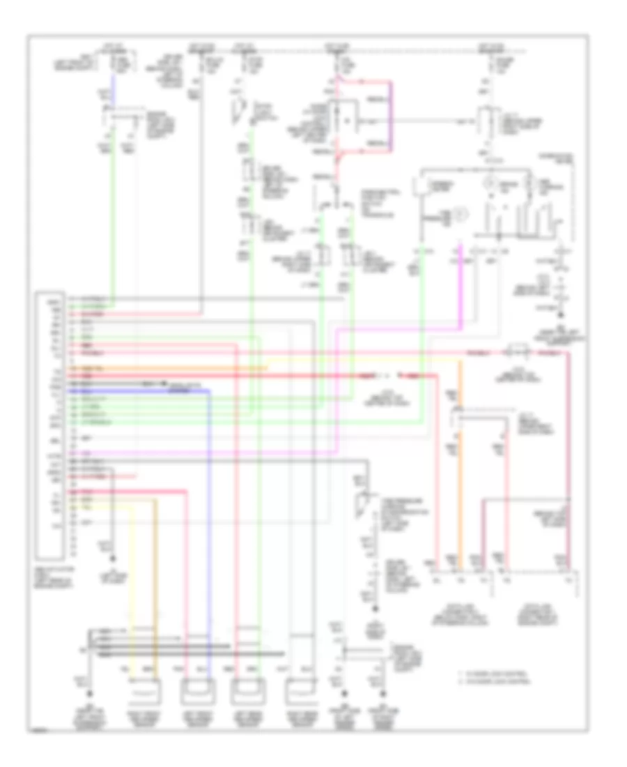
ANTI-LOCK BRAKES
Anti-lock Brake Wiring Diagrams for Toyota Sienna LE 2002
List of elements for Anti-lock Brake Wiring Diagrams for Toyota Sienna LE 2002:
- +bm
- +bs
- A11
- Abs actuator & ecu (left rear of engine compt)
- Abs fuse 60a
- Abs warning ind
- B j3
- B13
- B17
- B18
- Brake ind
- Brl
- C10
- C11
- Cig fuse 15a
- Combination meter
- D/g
- Data link connector 1 (right rear of engine compt)
- Data link connector 3 (below dash, right of steering column)
- Diode (w/ door lock control) (behind upper left center of dash)
- Driver side j/b 1 (behind dash, left of steering column)
- Ea (front side of right fender apron)
- Ecu-ig fuse 15a
- Ed (near the left front suspension support)
- Ee (front side of left fender apron)
- Engine room j/b 2 (left side of engine compt)
- Fl+
- Fl-
- Fr+
- Fr-
- Gauge fuse 10a
- Gnd1
- Gnd2
- Headlights system
- Hot at all times
- Hot in on or acc
- Hot in on or start
- I2 (behind top left side of dash)
- Ig (left side of dash)
- Ig1
- Ij (right side of dash)
- Init
- J/b 3 (behind instrument cluster)
- J/c 17 (behind upper right side of dash)
- J/c 2, j/c 3 (behind left side of dash)
- J/c 6 (behind top center of dash)
- J10
- J2 b
- Left front abs speed sensor
- Left rear abs speed sensor
- Nca
- Park/neutral position switch (on transaxle)
- Pkb
- Pnk
- R/b 7 (left front of engine compt)
- Red
- Right front abs speed sensor
- Right rear abs speed sensor
- Rl+
- Rl-
- Rr+
- Rr-
- Sil
- Speedo- meter
- Spo
- Stop fuse 15a
- Stop- light switch
- Stp
- Tire pressure ind
- Tire pressure warning standardization switch (left side of dash)
- W/ door lock control
- W/o door lock control
- Wtir
 Čeština
 Dansk
Dansk Deutsch
 Ελληνικά
 English
 Español
 Suomi
Suomi Français
 Français
 עברית
עברית Hrvatski
 Magyar
 Italiano
 日本語
日本語 한국어
한국어 Nederlands
 Polski
 Português
 Português
 Română
 Русский
 Slovenčina
 Slovenščina
 Svenska
 Türkçe
 中文 (中国)
 English