ANTI-LOCK BRAKES
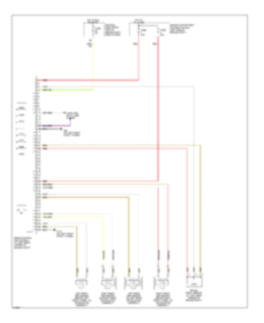
Anti-lock Brakes Wiring Diagram for Volvo S40 T-5 2006
 https://portal-diagnostov.com/license.html
Automotive Electricians Portal FZCO
Automotive Electricians Portal FZCO
https://portal-diagnostov.com/license.html
https://portal-diagnostov.com/license.html
Automotive Electricians Portal FZCO
Automotive Electricians Portal FZCO
List of elements for Anti-lock Brakes Wiring Diagram for Volvo S40 T-5 2006:
- Brake control module (bcm) (at left rear corner of engine compt)
- Brake pedal sensor (at left rear corner of engine compt)
- Central electronic module (behind right side of dash)
- Computer data lines system
- Engine compartment distribution box (left side of engine compt)
- Fuse 20a
- Fuse 30a
- Fuse 5a
- G119 (on left front strut tower)
- G80 (on left front strut tower)
- Hot at all times
- Hot in run or start
- Left front abs sensor (behind left front wheel, on spindle/hub assembly)
- Left rear abs sensor (on left rear spindle/hub assembly)
- Red
- Right front abs sensor (behind right front wheel, on spindle/hub assembly)
- Right rear abs sensor (on right rear spindle/hub assembly)
 Čeština
 Dansk
Dansk Deutsch
 Ελληνικά
 English
 English
 Español
 Suomi
Suomi Français
 Français
 עברית
עברית Hrvatski
 Magyar
 Italiano
 日本語
日本語 한국어
한국어 Nederlands
 Polski
 Português
 Português
 Română
 Русский
 Slovenčina
 Slovenščina
 Svenska
 Türkçe
 中文 (中国)
