ANTI-LOCK BRAKES
Anti-lock Brake Wiring Diagrams, with Dynamic Stability Control for Volvo V40 2000
 https://portal-diagnostov.com/license.html
Automotive Electricians Portal FZCO
Automotive Electricians Portal FZCO
https://portal-diagnostov.com/license.html
https://portal-diagnostov.com/license.html
Automotive Electricians Portal FZCO
Automotive Electricians Portal FZCO
List of elements for Anti-lock Brake Wiring Diagrams, with Dynamic Stability Control for Volvo V40 2000:
- A17
- Abs control module (right front corner of engine compt)
- Abs warning indicator
- B14
- B16
- B22
- Brake fluid level sensor (in brake master cylinder reservoir)
- Brake fluid level warning indicator
- Central electronic module (behind left end of dash)
- Dsa switch
- Dynamic stability control module (behind right end of dash)
- Dynamic stability on indicator
- E11
- Engine compartment fuse & relay box (left rear of engine compt)
- Engine control module (behind center of dash)
- Fuse a12 50a
- Fuse b11 10a
- Fuse b4 10a
- Fuse b6 15a
- G101 (front of right front fender)
- G202 (left side of dash)
- G302 (forward of center console)
- Hot at all times
- Hot in on
- Hot in on or start
- I14
- Instrument cluster
- Left front abs sensor (on wheel hub)
- Left rear abs sensor (on wheel hub)
- Nca
- Obd distribution rail (behind left side of dash)
- On-board diagnostic connector (below left center of dash)
- Passenger compartment fuse & relay box (behind left end of dash)
- Red
- Right front abs sensor (on wheel hub)
- Right rear abs sensor (on wheel hub)
- Speedo
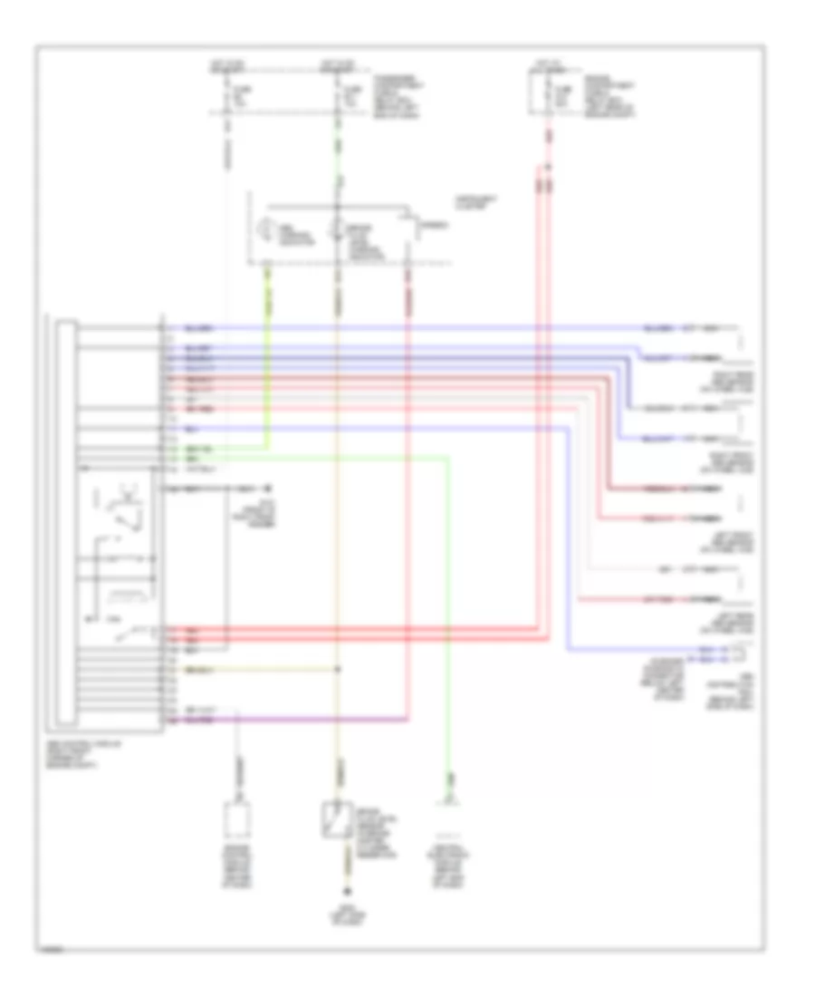
Anti-lock Brake Wiring Diagrams, without Dynamic Stability Control for Volvo V40 2000
List of elements for Anti-lock Brake Wiring Diagrams, without Dynamic Stability Control for Volvo V40 2000:
- A17
- Abs control module (right front corner of engine compt)
- Abs warning indicator
- B14
- B16
- Brake fluid level sensor (in brake master cylinder reservoir)
- Brake fluid level warning indicator
- Central electronic module (behind left end of dash)
- E11
- Engine compartment fuse & relay box (left rear of engine compt)
- Engine control module (behind center of dash)
- Fuse a12 50a
- Fuse b11 10a
- Fuse b4 10a
- G101 (front of right front fender)
- G202 (left side of dash)
- Hot at all times
- Hot in on or start
- Instrument cluster
- Left front abs sensor (on wheel hub)
- Left rear abs sensor (on wheel hub)
- Nca
- Obd distribution rail (behind left side of dash)
- On-board diagnostic connector (below left center of dash)
- Passenger compartment fuse & relay box (behind left end of dash)
- Red
- Right front abs sensor (on wheel hub)
- Right rear abs sensor (on wheel hub)
- Speedo

 Čeština
 Dansk
Dansk Ελληνικά
 English
 English
 Español
 Suomi
Suomi Français
 Français
 עברית
עברית Hrvatski
 Magyar
 Italiano
 日本語
日本語 한국어
한국어 Nederlands
 Polski
 Português
 Português
 Română
 Русский
 Slovenčina
 Slovenščina
 Svenska
 Türkçe
 中文 (中国)