ANTI-THEFT
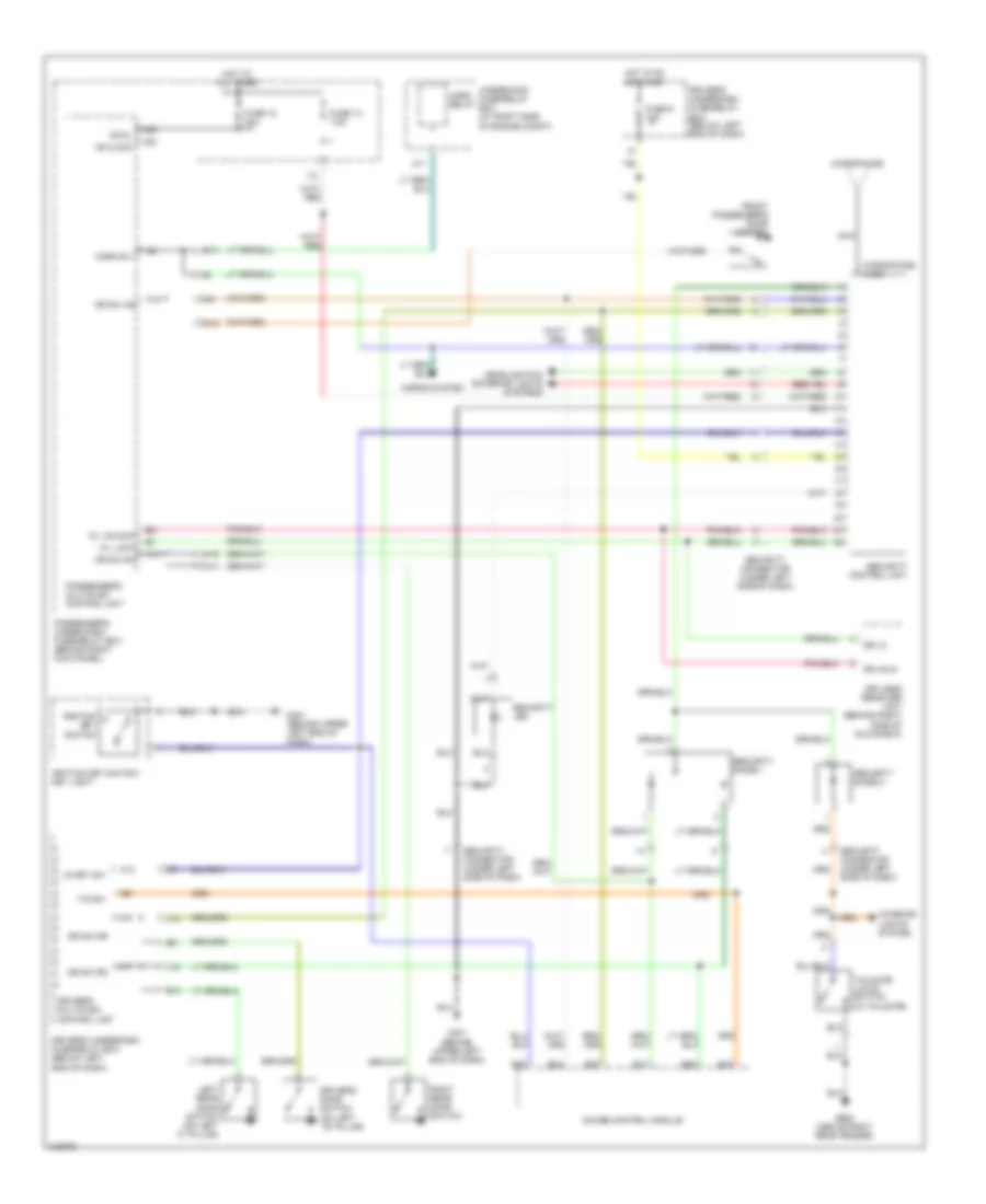
Forced Entry Wiring Diagram, EX, EX-L (1 of 2) for Honda Pilot EX 2006
 https://portal-diagnostov.com/license.html
Automotive Electricians Portal FZCO
Automotive Electricians Portal FZCO
https://portal-diagnostov.com/license.html
https://portal-diagnostov.com/license.html
Automotive Electricians Portal FZCO
Automotive Electricians Portal FZCO
List of elements for Forced Entry Wiring Diagram, EX, EX-L (1 of 2) for Honda Pilot EX 2006:
- (below right front seat) g651
- (not used)
- +b clock
- +b d/l
- A10
- A11
- A12
- A13
- A14
- A15
- A16
- A17
- A21
- A22
- A23
- A24
- Antenna
- B11
- B14
- B21
- B22
- Bus (door/dr)
- Bus as
- Bus dr
- C14
- C16
- C20
- D/l lock
- D/l unlck dr
- D/l unlock
- Door lock
- Door unlock
- Dr sw as
- Dr sw dr
- Dr sw ra
- Dr sw rd
- Driver's multiplex control unit
- Driver's under-dash fuse/relay box (below left end of dash)
- E10
- E15
- E17
- Front passenger's door lock actuator (rear of front passenger's door)
- Fuse 12 20a
- Fuse 13 7.5a
- G15
- G201 (behind right headlight)
- G401 (behind upper left end of dash)
- G501
- G503 (behind right end of dash)
- G601 (below left front seat)
- G651 (below right front seat)
- G652 (above right rear fender)
- Gnd
- H/l rly+
- H14
- Headlights system
- Hood sw
- Horn rly
- Horns system
- Hot at all times
- I12
- I14
- Ig key sw
- Ig1
- Ig1 meter
- Ignition key switch
- Ignition key switch/ key light
- Instrument cluster system
- Interior lights system
- Intrlt
- K/c as lock
- K/c as unlock
- K/l lock
- K/l panic
- K/l unlock
- Keyless receiver unit (behind right side of glove box)
- Left rear door lock knob switch (at rear of left rear door)
- M19
- Nca
- Panic
- Passenger's multiplex control unit
- Passenger's under-dash fuse/relay box (behind right kick panel)
- Pnk
- Radio sw
- Rem as lock
- Rem as unlock
- Right rear door lock knob switch
- Scty in
- Security hood switch (at center front of engine compt)
- Sgnd
- Sil as unlock
- Sil ra unlock
- Sil rd unlock
- Sound systems
- T/g sw
- Tailgate latch switch (in tailgate)
- Tailgate lights
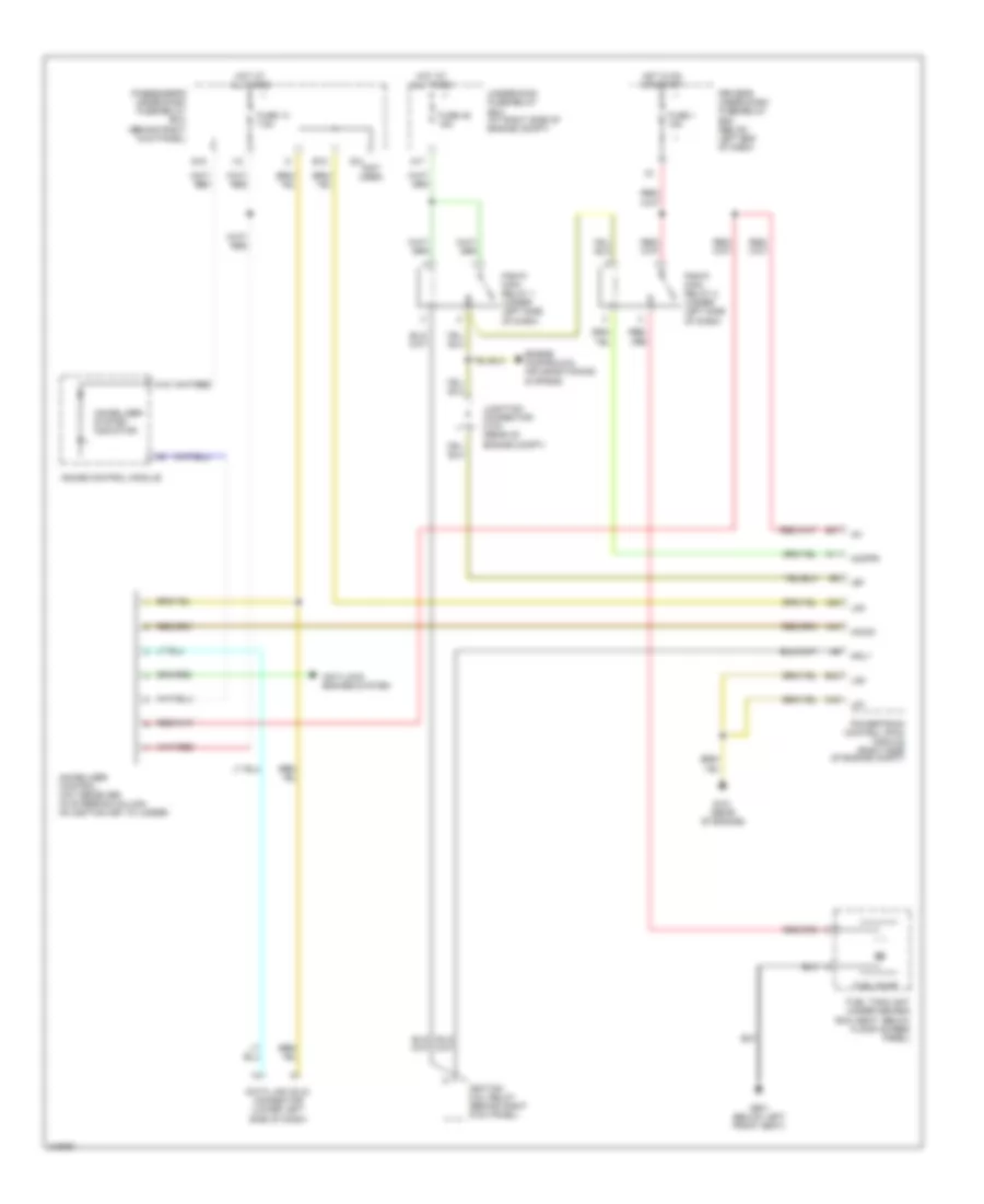
Forced Entry Wiring Diagram, EX, EX-L (2 of 2) for Honda Pilot EX 2006
List of elements for Forced Entry Wiring Diagram, EX, EX-L (2 of 2) for Honda Pilot EX 2006:
- A12
- A15
- A16
- A17
- A18
- B30
- Door multiplex control unit (in driver's door)
- Driver's door key cylinder switch (in driver's door)
- Driver's door lock actuator (at rear of driver's door)
- Driver's door lock knob switch (at rear of driver's door)
- Driver's door lock switch
- Driver's door switch (on left ``b" pillar)
- Driver's underdash fuse/relay box (below left end of dash)
- Front passenger's door lock knob switch
- Front passenger's door lock switch
- Front passenger's door switch (on right ``b" pillar)
- Fuse 9 10a
- G401 (behind upper left end of dash)
- Gauge control module
- H16
- Hot in on or start
- Interior lights system
- K13
- L13
- Left rear door lock actuator (at rear of left rear door)
- Left rear door switch (on left ``c" pillar)
- Lock
- Mpx-dr
- Pnk
- Right rear door lock actuator (rear of right rear door)
- Right rear door switch
- Security indicator
- Tailgate lock actuator (near center of tailgate)
- Unlock
- Vbu
Forced Entry Wiring Diagram, LX for Honda Pilot EX 2006
List of elements for Forced Entry Wiring Diagram, LX for Honda Pilot EX 2006:
- +b clock
- +b d/l
- A11
- A13
- A14
- A15
- A16
- A17
- A23
- A24
- B14
- B16
- B17
- B27
- B28
- B34
- B35
- C14
- C16
- Dr lk
- Dr sw as
- Dr sw dr
- Dr sw ra
- Dr sw rd
- Dr unlk
- Driver's door switch (on left ``b" pillar)
- Driver's multiplex control unit
- Driver's underdash fuse/relay box (below left end of dash)
- E10
- Front passenger's door switch
- Fuse 12 20a
- Fuse 13 7.5a
- Fuse 9 10a
- G401 (behind upper left end of dash)
- G652 (above right rear fender)
- Gauge control module
- H16
- Headlights & exterior lights systems
- Horn relay
- Horn rly
- Horns system
- Hot at all times
- Hot in on or start
- I12
- Ig key sw
- Ignition key switch
- Ignition key switch/ key light
- Interior lights system
- J14
- J15
- K/l lock
- K/l unlock
- Keyless receiver unit (behind right side of glove box)
- Left rear door switch (on left "c" pillar)
- Microphone
- Microphone jack
- Nca
- Passenger's multiplex control unit
- Passenger's under-dash fuse/relay box (behind right kick panel)
- Right rear door switch
- Security connector (under left side of dash)
- Security control unit
- Security diode 1
- Security diode 2
- Security led
- T/g sw
- Tailgate latch switch (in tailgate)
- Underhood fuse/relay box (at right side of engine compt)
Immobilizer Wiring Diagram for Honda Pilot EX 2006
List of elements for Immobilizer Wiring Diagram for Honda Pilot EX 2006:
- (not used)
- A11
- A17
- A1o
- A22
- A44
- Anti-lock brakes system
- B18
- B37
- B43
- C40
- Data link (dlc) connector (lower left side of dash)
- Driver's under-dash fuse/relay box (below left end of dash)
- Engine controls & air conditioning systems
- Fuel pump
- Fuel tank unit (under second row seat, below floor access panel)
- Fuse 1 15a
- Fuse 13 7.5a
- Fuse 46 15a
- G101 (rear of engine)
- G14
- G16
- G601 (below left front seat)
- Gauge control module
- Hot at all times
- Hot in on or start
- I12
- Ig1
- Ignition coil relay (behind right kick panel)
- Igp
- Immobilizer control unit receiver (in steering column, on ignition key cylinder)
- Immobilizer system indicator
- Imocd
- Imofpr
- Junction connector c103 (rear of engine compt)
- Lg1
- Lg2
- Lg3
- Mrly
- Passenger's under-dash fuse/relay box (behind right kick panel)
- Pgm-fi main relay 1 (under left side of dash)
- Pgm-fi main relay 2 (under left side of dash)
- Powertrain control (pcm) module (right side of engine compt)
- Underhood fuse/relay box (at right side of engine compt)

 Čeština
 Dansk
Dansk Deutsch
 Ελληνικά
 English
 Español
 Suomi
Suomi Français
 Français
 עברית
עברית Hrvatski
 Magyar
 Italiano
 日本語
日本語 한국어
한국어 Nederlands
 Polski
 Português
 Português
 Română
 Русский
 Slovenčina
 Slovenščina
 Svenska
 Türkçe
 中文 (中国)