ANTI-THEFT
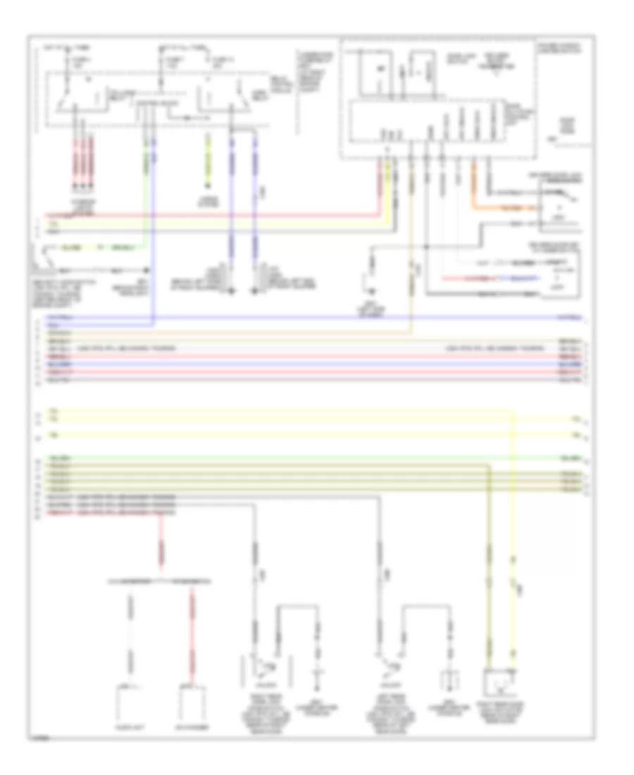
Forced Entry Wiring Diagram (1 of 3) for Honda Ridgeline RTL 2014
 https://portal-diagnostov.com/license.html
Automotive Electricians Portal FZCO
Automotive Electricians Portal FZCO
https://portal-diagnostov.com/license.html
https://portal-diagnostov.com/license.html
Automotive Electricians Portal FZCO
Automotive Electricians Portal FZCO
List of elements for Forced Entry Wiring Diagram (1 of 3) for Honda Ridgeline RTL 2014:
- (not used)
- (usa: rts, rtl, se; canada: touring)
- 20a
- 7.5a
- A10
- A19
- A20
- Anti-theft system
- As unlock
- B-can
- Body controller area network transceiver
- C408
- C453
- C454
- D11
- Door lock knob
- Door lock switch
- Dr unlock
- Driver's door switch (on left "b" pillar)
- Drswas
- Drswdr
- Drswra
- Drswrd
- E10
- E14
- E15
- Front passenger's door lock knob switch (usa: rts, rtl, se; canada: touring)
- Front passenger's door switch (on right "b" pillar)
- Front passenger's power window switch/door lock switch
- Fuse 21
- Fuse 2a
- Fuse 7.5a
- Fuse 8
- G401 (left side of dash)
- G402 (right end of dash)
- G403 (left side of dash)
- G501 (under center console)
- Gauge control module
- H10
- H12
- H13
- Hot at all times
- Hot in on or start
- Ig1
- Ignition key switch
- Ignition key switch/key light
- K11
- K12
- Left rear door switch (on left "c" pillar)
- Lock
- Micu
- Micu gnd
- Multi- information display (mid) unit
- N28
- N38
- N44
- P1 sg-1
- P13 ig key sw
- P25 rem as lock
- P27 scty in
- P29 sil as unlock
- P9 rem as unlock
- Q11 tailgate sw
- Q12 trunk handle sw
- Q2 sil ra unlock
- Q3 sil rd unlock
- Q4 trunk unlock
- Right rear door switch (on right "c" pillar)
- Security light ind (usa: rts, rtl, se; canada: touring)
- Trunk act
- Trunk sw
- Under-dash fuse/relay box (at left kick panel)
- Unlock
- Vbu
- Warning drive circuit
- X34
- X35
Forced Entry Wiring Diagram (2 of 3) for Honda Ridgeline RTL 2014
List of elements for Forced Entry Wiring Diagram (2 of 3) for Honda Ridgeline RTL 2014:
- (usa: rts, rtl, se; canada: touring)
- 15a
- 20a
- 7.5a
- A18
- Audio unit
- C203
- C454
- C506
- C507
- Cd changer
- Control block
- Door lock knob
- Door lock switch
- Door multiplex control unit
- Driver's door key cylinder switch
- Driver's door lock knob switch
- Fuse 13
- Fuse 4
- Fuse 7
- G201 (behind right headlight)
- G401 (left side of dash)
- G501 (under center console)
- H14
- H15
- High horn (behind left side of front bumper)
- Horn relay
- Horns system
- Hot at all times
- Ign
- Interior lights system
- Key
- Key lock
- Key unlock
- Keyless entry transmitter
- Knob lock
- Knob unlock
- Left rear door lock knob switch (usa: rts, rtl, se; canada: touring) (rear of left rear door)
- Lock
- Low horn (behind left end of front bumper)
- Pg1
- Power window master switch
- Relay control module
- Right rear door lock actuator (rear of right rear door)
- Right rear door lock knob switch (usa: rts, rtl, se; canada: touring) (rear of right rear door)
- Security hood switch (usa: rts, rtl, se; canada: touring) (center front of engine compt)
- Sgnd
- Taillight relay
- Under-hood fuse/relay box (at right rear of engine compt)
- Unlock
- Vbu
- W/ navigation
- W/o navigation
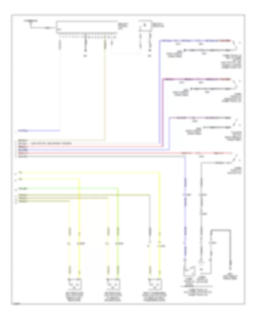
Forced Entry Wiring Diagram (3 of 3) for Honda Ridgeline RTL 2014
List of elements for Forced Entry Wiring Diagram (3 of 3) for Honda Ridgeline RTL 2014:
- (usa: rts, rtl, se; canada: touring)
- C403
- C408
- C453
- C506
- C509
- C510
- C601
- Driver's door lock actuator (at rear of driver's door)
- Front passenger's door lock actuator (at rear of front passenger's door)
- G51
- G601 (left side of cargo area)
- G602 (right side of cargo area)
- In-bed trunk lid actuator
- In-bed trunk lid actuator/latch switch (in-bed trunk lid)
- In-bed trunk lid handle switch (in-bed trunk lid)
- In-bed trunk lid key cylinder switch (usa: rts, rtl, se; canada: touring) (in-bed trunk lid)
- In-bed trunk lid latch switch
- In-bed trunk lid main switch
- Left rear door lock actuator (rear of left rear door)
- Mic
- Microphone
- Nca
- Security control unit
- Security indicator
- Tailgate switch (right rear of cargo area)
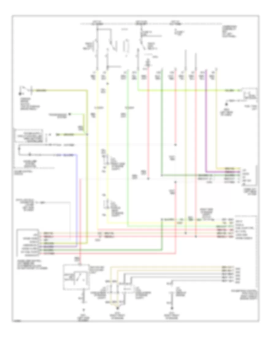
Immobilizer Wiring Diagram for Honda Ridgeline RTL 2014
List of elements for Immobilizer Wiring Diagram for Honda Ridgeline RTL 2014:
- (lower left side of dash)
- (right side of engine compt) j/c c101
- +b backup
- A11
- A19
- A41
- A46
- B21
- B23
- B40
- B41
- B42
- C18
- C204
- C205
- C402
- C41
- Data link (dlc) connector
- Diag-h
- E12
- E13
- Fuel pump
- Fuel pump ctrl
- Fuel tank unit
- Fuse 19 15a
- Fuse 7 7.5a
- G101 (right front of engine)
- G401 (left side of dash)
- G502 (left rear of cabin)
- Gauge control module
- Gnd
- H/brake sw
- Hot at all times
- Hot in on or start
- Ig key sw
- Ig1
- Ig1 fuel pump
- Ign in
- Ignition key switch
- Ignition key switch/key light
- Immobi alarm
- Immobi code
- Immobi code in
- Immobilizer control unit receiver (in steering column, on ignition key cylinder)
- Immobilizer system indicator
- Imocd
- Imoes unit (left rear of cab)
- J/c c101 (right side of engine compt)
- J/c c103 (middle rear of engine compt)
- J/c c104 (middle rear of engine compt)
- J/c c105 (rear of engine)
- Key sw
- Lg1
- Lg3
- Logic gnd
- Micu
- P13
- Parking brake switch (top of parking brake pedal)
- Pgm-fi main relay 1
- Pgm-fi main relay 2
- Powertrain control (pcm) module (right side of engine compt)
- Pwr in
- Rly ctrl
- Transmissions system
- Under-dash fuse/relay box (at left kick panel)
- X35
- X38

 Čeština
 Dansk
Dansk Deutsch
 Ελληνικά
 English
 Español
 Suomi
Suomi Français
 Français
 עברית
עברית Hrvatski
 Magyar
 Italiano
 日本語
日本語 한국어
한국어 Nederlands
 Polski
 Português
 Português
 Română
 Русский
 Slovenčina
 Slovenščina
 Svenska
 Türkçe
 中文 (中国)