ANTI-THEFT
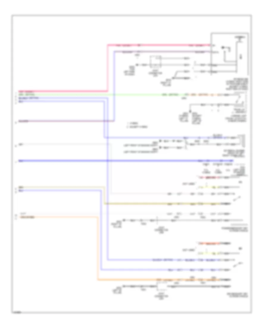
Forced Entry Wiring Diagram, Except Hybrid (1 of 2) for Hyundai Sonata Limited 2014
 https://portal-diagnostov.com/license.html
Automotive Electricians Portal FZCO
Automotive Electricians Portal FZCO
https://portal-diagnostov.com/license.html
https://portal-diagnostov.com/license.html
Automotive Electricians Portal FZCO
Automotive Electricians Portal FZCO
List of elements for Forced Entry Wiring Diagram, Except Hybrid (1 of 2) for Hyundai Sonata Limited 2014:
- B-can
- B/a horn rly ctrl
- Burglar alarm relay ctrl
- Computer data lines system
- Door lock
- Door lock relay
- Door lock relay ctrl
- Door lock sw lock
- Door lock sw unlock
- Door lock switch
- Door unlock
- Door unlock relay
- Door unlock relay control
- Dr lk
- Dr lock fuse 20a
- Dr unlk
- Driver door key unlock signal
- Driver door lock actuator
- Driver door lock/ unlock signal
- Driver/ pass door key lock signal
- Fd01
- Fd02
- Fd11
- Fd12
- Gf02 (left "b" pillar)
- Gf03 (right "b" pillar)
- Gf04 (left "c" pillar)
- Gf05 (right "c" pillar)
- Gm03 (top left side of dash)
- High
- Hood sw
- Hot at all times
- I/p junction box (left side of dash)
- I/p-a
- I/p-b
- I/p-d
- I/p-e
- I/p-f
- Ips control module
- Joint connector uda
- Joint connector udb
- Key lk
- Key unlk
- Left rear door lock actuator
- Left rear door lock/ unlock signal
- Low
- Mf11
- Pass door key unlock signal
- Pass door lock/ unlock signal
- Passenger door lock actuator
- Passenger power window switch
- Pnk
- Power connector
- Power window main switch
- Red
- Right rear door lock actuator
- Right rear door lock/ unlock signal
- Room lp fuse 10a
- Starting/ charging system
- Two turn unlock control
- W/o smart key
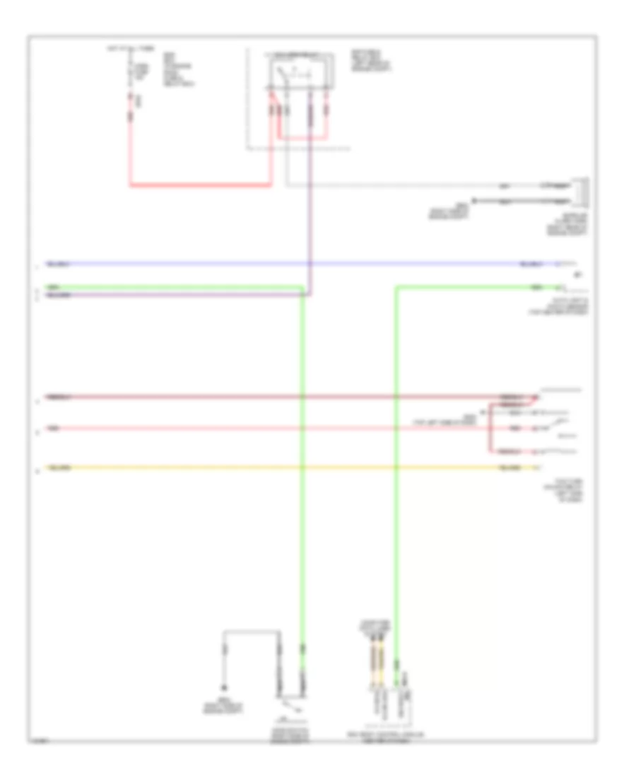
Forced Entry Wiring Diagram, Except Hybrid (2 of 2) for Hyundai Sonata Limited 2014
List of elements for Forced Entry Wiring Diagram, Except Hybrid (2 of 2) for Hyundai Sonata Limited 2014:
- (left side of dash)
- Auto light & photo sensor (top center of dash)
- B-can hi
- B-can low
- B/a horn relay
- Bcm (body control module) (center of dash)
- Burglar alarm horn (right rear of engine compt)
- Computer data lines system
- E/r fuse & relay box (left rear of engine compt)
- E/r-b
- Ems box (in engine room fuse & relay box)
- Ge04 (right side of engine compt)
- Gm03 (top left side of dash)
- Hood switch (right side of engine compt)
- Horn fuse 15a
- Hot at all times
- M02-b ind security
- Nca
- Red
- Two turn unlock relay
Forced Entry Wiring Diagram, Hybrid (1 of 2) for Hyundai Sonata Limited 2014
List of elements for Forced Entry Wiring Diagram, Hybrid (1 of 2) for Hyundai Sonata Limited 2014:
- B-can
- B/ horn rly ctrl
- Computer data lines system
- Door lock
- Door lock relay
- Door lock relay ctrl
- Door lock switch
- Door unlock
- Door unlock relay
- Door unlock relay control
- Dr lk
- Dr lock fuse 20a
- Dr unlk
- Driver door key unlock signal
- Driver door lock actuator
- Driver door lock/ unlock signal
- Driver/ pass door key lock signal
- Ef01
- Em11
- Fd01
- Fd02
- Fd11
- Fd12
- Gf02 (left "b" pillar)
- Gf03 (right "b" pillar)
- Gf04 (left "c" pillar)
- Gf05 (right "c" pillar)
- Gm03 (top left side of dash)
- High
- Hood sw
- Hot at all times
- I/p junction box (left side of dash)
- I/p-a
- I/p-b
- I/p-d
- I/p-e
- I/p-f
- Ips control module
- Joint connector uda
- Joint connector udb
- Key lk
- Key unlk
- Left rear door lock actuator
- Left rear door lock/ unlock signal
- Lock
- Low
- Pass door key unlock signal
- Pass door lock/ unlock signal
- Passenger door lock actuator
- Passenger power window switch
- Pnk
- Power connector
- Power window main switch
- Red
- Right rear door lock actuator
- Right rear door lock/ unlock signal
- Room lamp fuse 10a
- Two turn unlock control
- Unlock
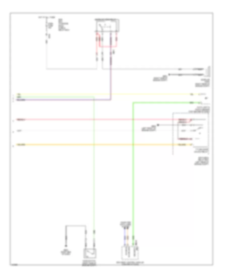
Forced Entry Wiring Diagram, Hybrid (2 of 2) for Hyundai Sonata Limited 2014
List of elements for Forced Entry Wiring Diagram, Hybrid (2 of 2) for Hyundai Sonata Limited 2014:
- Auto light & photo sensor (top center of dash)
- B-can hi
- B-can low
- Bcm (body control module) (center of dash)
- Burglar horn (right rear of engine compt)
- Burglar horn relay
- Computer data lines system
- E/r fuse & relay box (left rear of engine compt)
- E/r-b
- Em11
- Ems box (in engine room fuse & relay box)
- Ge03 (right end of dash)
- Ge04 (right side of engine compt)
- Ge08 (left front of engine compt)
- Hood switch (right side of engine compt)
- Horn fuse 15a
- Hot at all times
- M02-b ind security
- Nca
- Red
- T/turn door unlock relay
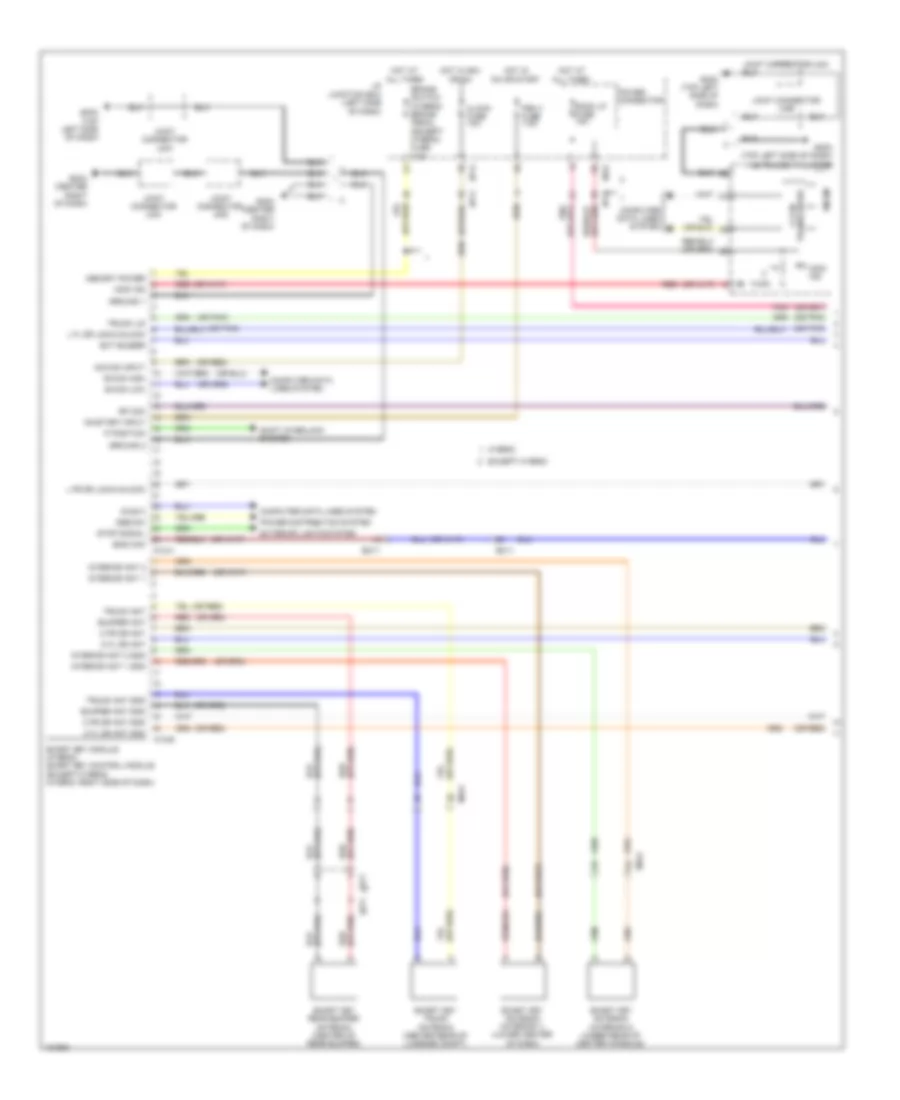
Immobilizer Wiring Diagram, with Smart Key System (1 of 2) for Hyundai Sonata Limited 2014
List of elements for Immobilizer Wiring Diagram, with Smart Key System (1 of 2) for Hyundai Sonata Limited 2014:
- (or pnk)
- (or red)
- Acc/on input
- B-can high
- B-can low
- Brake switch (hybrid) brake pedal (except hybrid) fuse 7.5a
- Bumper ant
- Bumper ant gnd
- C-can transceiver
- Clock fuse 10a
- Computer data lines system
- Diag k
- Ec11
- Em11
- Ems com
- Except hybrid
- Ext buzzer
- Exterior lights system
- Fr11
- Gm03 (top left side of dash)
- Gm04 (center right of dash)
- Ground 1
- Ground 2
- Hot at all times
- Hot in acc or on
- Hot in on or start
- Hybrid
- I/p junction box (left side of dash)
- I/p-e
- I/p-g
- Immo ind
- Instrument cluster
- Interior ant 1
- Interior ant 1 gnd
- Interior ant 2
- Interior ant 2 gnd
- Joint connector uma
- Joint connector umb
- Joint connector umc
- Joint connector umd
- L fl dr lock/unlock
- L fr dr lock/unlock
- M12-a
- M12-b
- Memory power
- Mf61
- Micom
- O fl dr ant
- O fl dr ant gnd
- O fr dr ant
- O fr dr ant gnd
- Of dash)
- On/start input
- P position
- Pdm 3 fuse 7.5a
- Pnk
- Power connector
- Power distribution system
- Red
- Rf com
- Room lp fuse 10a
- Shift interlock system
- Smart key antenna (interior 1) (lower center
- Smart key antenna (interior 2) (under rear of center console)
- Smart key module (hybrid) smart key control module (except hybrid) (hybrid: right side of dash)
- Smart key rear bumper antenna (center of rear bumper)
- Smart key trunk antenna (center rear of luggage compt)
- Ssb sw
- Stop signal
- Trunk ant
- Trunk ant gnd
- Trunk lid
Immobilizer Wiring Diagram, with Smart Key System (2 of 2) for Hyundai Sonata Limited 2014
List of elements for Immobilizer Wiring Diagram, with Smart Key System (2 of 2) for Hyundai Sonata Limited 2014:
- (not used)
- (or pnk)
- (or red)
- 2.0l turbo
- 2.4l
- 2.4l hybrid
- Antenna
- Chg-ag
- Chg-k
- Chtg-ag
- Data
- Driver smart key outside handle
- Em61
- Except hybrid
- External buzzer (front of left front wheelwell)
- Fd01
- Fd02
- Ge02 (left front of engine compt)
- Gf02 (except hybrid) (left "b" pillar)
- Gf02 (left "b" pillar)
- Gf03 (right "b" pillar)
- Gf04 (hybrid) (left "c" pillar)
- Gf05 (right "c" pillar)
- Gm03 (top left side of dash)
- Gnd
- Hybrid
- Joint connector uda
- Joint connector udb
- Joint connector uma
- License lamp (trunk lid switch & rear camera)
- Mcu
- Mf61
- Nca
- Passenger smart key outside handle
- Pcm (left side of engine compt)
- Pnk
- Rf receiver (hybrid: right side of package shelf) (except hybrid: right end of dash)
- Trunk lid switch
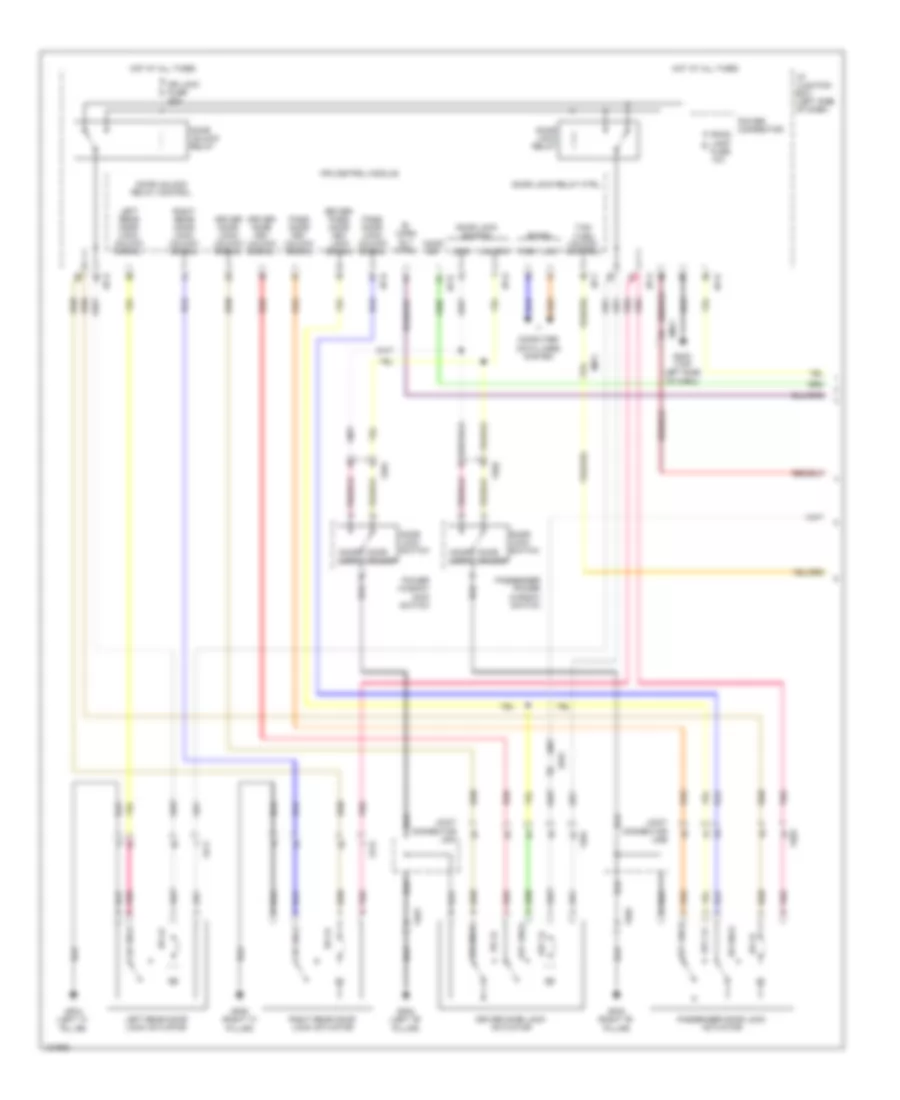
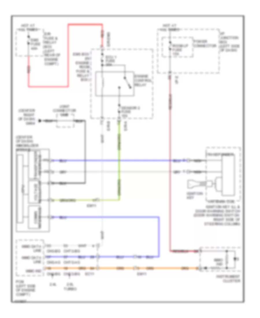
Immobilizer Wiring Diagram, without Smart Key System for Hyundai Sonata Limited 2014
List of elements for Immobilizer Wiring Diagram, without Smart Key System for Hyundai Sonata Limited 2014:
- (+)
- (-)
- (center of dash) immobilizer module
- (center right of dash) gm04
- 2.0l
- 2.4l
- Antenna coil
- Chg-ag
- Chg-bg
- Chtg-ag
- Chtg-bg
- Cpu
- E/r fuse & relay box (left rear of engine compt)
- E/r-a
- E/r-b
- E/r-ems
- Ec11
- Ecu 1 fuse 30a
- Em11
- Ems box (in engine room fuse & relay box)
- Ems fuse 40a
- Engine control relay
- Hot at all times
- I/p junction box (left side of dash)
- I/p-e
- Ignition key
- Ignition key ill & door warning switch (door warning switch: right side of steering column)
- Immo data line
- Immo ind
- Instrument cluster
- Interface comms
- Interface transponder
- Joint connector umb
- Nca
- Pcm (left side of engine compt)
- Power connector
- Red
- Regulator voltage
- Room lp fuse 15a
- Sensor 2 fuse 15a
- Transponder
- Turbo

 Čeština
 Dansk
Dansk Deutsch
 Ελληνικά
 English
 Español
 Suomi
Suomi Français
 Français
 עברית
עברית Hrvatski
 Magyar
 Italiano
 日本語
日本語 한국어
한국어 Nederlands
 Polski
 Português
 Português
 Română
 Русский
 Slovenčina
 Slovenščina
 Svenska
 Türkçe
 中文 (中国)