ANTI-THEFT
Forced Entry Wiring Diagram for Hyundai XG350 2003
 https://portal-diagnostov.com/license.html
Automotive Electricians Portal FZCO
Automotive Electricians Portal FZCO
https://portal-diagnostov.com/license.html
https://portal-diagnostov.com/license.html
Automotive Electricians Portal FZCO
Automotive Electricians Portal FZCO
List of elements for Forced Entry Wiring Diagram for Hyundai XG350 2003:
- (w/ ims)
- (w/o ims)
- 87a
- Assister door module (integral with power window/ door switch assembly, on right front door)
- Burglar alarm relay
- Check connector (at lower left side of dash)
- Code save
- D04
- D05
- D29
- D30
- Data
- Driver door module (integral with power window/ door switch assembly, on left front door)
- Drl control module (on right front of engine compartment, near engine mount)
- Drl fuse 15a
- Engine compartment junction block (on left front of engine compt)
- Etacm
- Exterior lights system
- Fuse 10a
- G01 (behind right headlight)
- G03 (on left "a" pillar, near passenger compt junction block)
- G05 (on right "a" pillar, near crash bar)
- G07 (at left floorpanel crossmember)
- G08 (on left side of package shelf)
- G09 (on right side of package shelf)
- Haz rly cntrl
- Hazard relay
- Hood switch (on right front of engine compartment)
- Hood switch in
- Hot at all times
- Hot in start
- J/c m09 (center of dash)
- Je01
- Jm01
- Jm05
- Jm09
- Joint connector d13
- Joint connector m99
- Left door unlock switch
- Left joint connector d12
- Left rear door lock actuator
- M33-1
- M33-2
- M33-3
- Multipurpose
- Nca
- Passenger compartment junction block (behind left end of dash)
- Rear dr input
- Red
- Relay control
- Right door unlock switch
- Right rear door lock actuator
- Signal ground
- Siren (at right front corner of engine compartment)
- Siren control
- Starting/ charging system
- Trunk lid solenoid (on center of trunk, beside latch)
- Trunk unlock switch
- Trunk unlock switch in
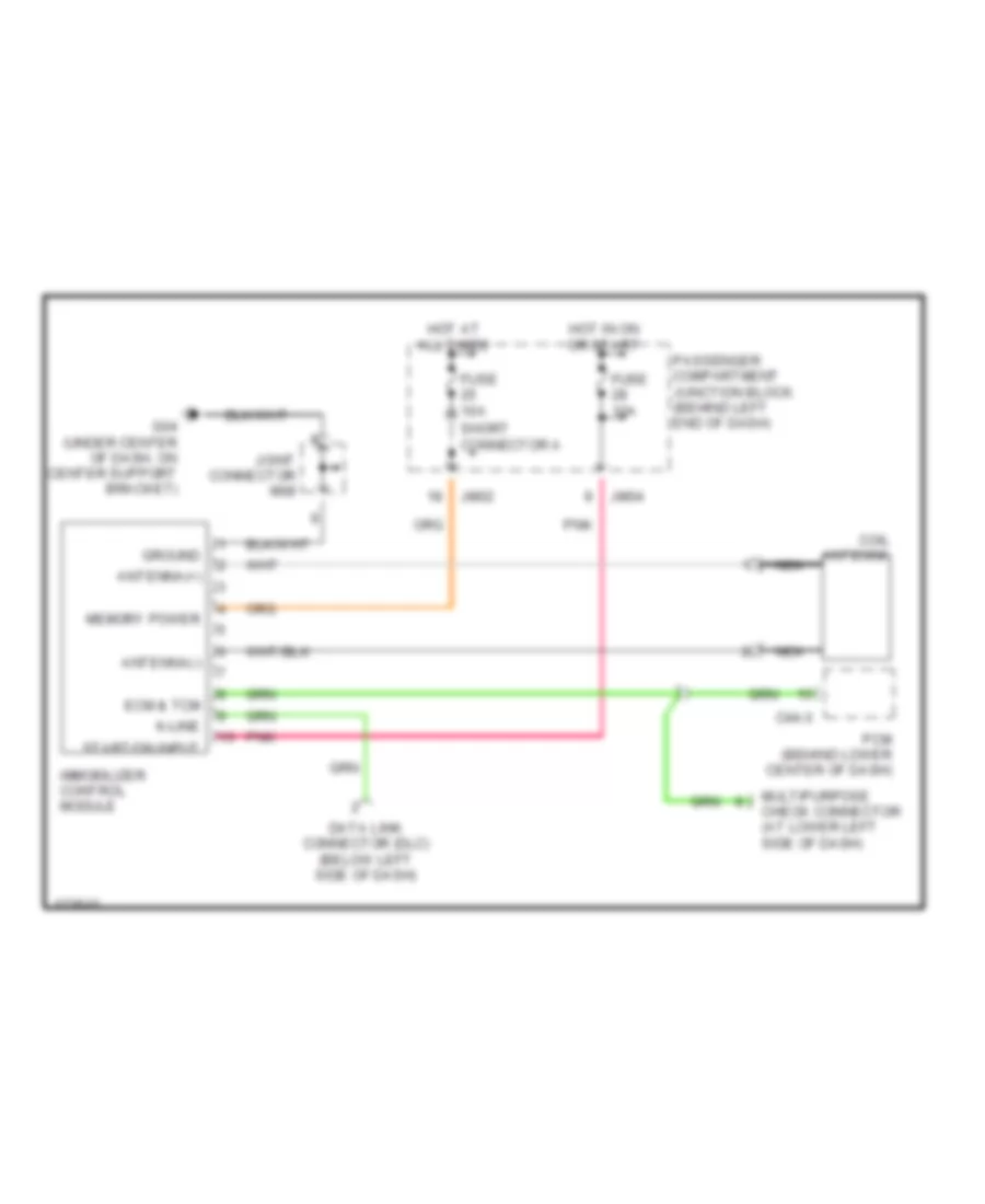
Immobilizer Wiring Diagram for Hyundai XG350 2003
List of elements for Immobilizer Wiring Diagram for Hyundai XG350 2003:
- Antenna(+)
- Antenna(-)
- C44-3
- Coil antenna
- Data link connector (dlc) (below left side of dash)
- Ecm & tcm
- Fuse 10a
- G04 (under center of dash, on center support bracket)
- Ground
- Hot at all times
- Hot in on or start
- Immobilizer control module
- Jm02
- Jm04
- Joint connector m08
- K-line
- Memory power
- Multipurpose check connector (at lower left side of dash)
- Nca
- Passenger compartment junction block (behind left end of dash)
- Pcm (behind lower center of dash)
- Pnk
- Short connector a
- Start/on input

 Čeština
 Dansk
Dansk Deutsch
 Ελληνικά
 English
 Español
 Suomi
Suomi Français
 Français
 עברית
עברית Hrvatski
 Magyar
 Italiano
 日本語
日本語 한국어
한국어 Nederlands
 Polski
 Português
 Português
 Română
 Русский
 Slovenčina
 Slovenščina
 Svenska
 Türkçe
 中文 (中国)