ANTI-THEFT
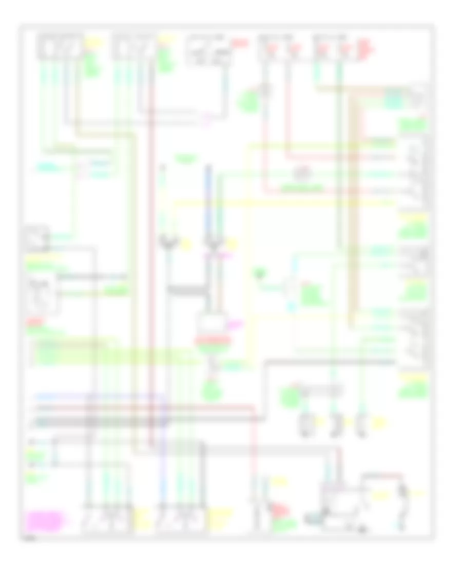
Anti-theft Wiring Diagram (1 of 2) for Infiniti I30 t 1998
 https://portal-diagnostov.com/license.html
Automotive Electricians Portal FZCO
Automotive Electricians Portal FZCO
https://portal-diagnostov.com/license.html
https://portal-diagnostov.com/license.html
Automotive Electricians Portal FZCO
Automotive Electricians Portal FZCO
List of elements for Anti-theft Wiring Diagram (1 of 2) for Infiniti I30 t 1998:
- (a/t)
- (left "b" pillar)
- (m/t)
- (right "b" pillar)
- (right kick panel)
- (right kick panel) g203
- 10g
- 16l
- A/t
- Accessory
- Alarm
- Between full
- Body control module (below center of dash)
- Data line a1
- Data line a2
- Door switch
- Driver door control unit (in driver's door)
- Driver side front door lock actuator
- Fender)
- Fuse 10a
- Fuse 7.5a
- Fuse and fusible link box (left side of engine compt)
- Fuse block (behind left side of dash)
- G100 (left front fender)
- G101 (right front
- G202 (left side of dash)
- G203
- G305
- G305 (right "b" pillar)
- G308
- G308 (left "b"
- Ground
- Hood switch
- Hot at all times
- Hot in acc or on
- Hot in on or start
- Hot in start
- Ignition
- Left front door switch
- Left rear door control unit (in left rear door)
- Left rear door lock actuator
- Left rear door switch
- Lock sw
- M/t
- Passenger door control unit (in right front door)
- Passenger side front door lock actuator
- Pillar)
- Pnk
- Right rear door control unit (in right rear door)
- Right rear door lock actuator
- Right rear door switch
- Security indicator lamp
- Start interrupt
- Stroke & normal
- Theft indicator
- Theft warning relay (relay box 1, right side of engine compt)
- Trunk lid key cylinder switch
- Trunk room lamp switch
- Trunk switch
- Trunk tamper sw
- Trunk unlock
- Unlock sens
- Unlock sw
Anti-theft Wiring Diagram (2 of 2) for Infiniti I30 t 1998
List of elements for Anti-theft Wiring Diagram (2 of 2) for Infiniti I30 t 1998:
- (canada only)
- (in relay box 1, right side of engine compt)
- (right kick panel)
- A/t
- Acc
- Ant
- Battery
- Canada
- Clutch interlock relay (m/t) (relay box 2, left front of engine compt)
- Clutch interlock switch (behind dash, above clutch pedal)
- Data line a1
- Daytime running light control unit (right front of engine compt)
- Driver's door key cylinder switch
- Fuse 10a
- Fuse 15a
- Fuse 7.5a
- Fuse and fusible link box
- G120 (right side of engine)
- G202 (left side of dash)
- G203
- Headlights system
- High horn
- Horn relay (in relay box 2, left front of engine compt)
- Horns system
- Hot at all times
- Ignition switch
- Inhibitor relay (a/t) (relay box 2, left front of engine compt)
- Inhibitor switch (left rear side of transaxle)
- J/c 2 (in fusible link box, left side of engine compt)
- J/c 4 (in fusible link box, left side of engine compartment)
- J/c 5 (in relay box 1, right side of engine compt)
- J/c 6
- J/c 7 (in relay box1, right side of engine compt)
- J/c 8 (in relay box 1, right side of engine compt)
- Left head- lamp
- Lock
- Lock-between full
- Low horn
- M/t
- Multi remote control unit (right side of luggage compt)
- Nca
- Passenger's front door key cylinder switch
- Right head- lamp
- Run
- Start
- Starter motor
- Stroke & normal key withdrawn
- Stroke & normal unlock-between full
- Theft warning horn
- Theft warning horn relay (in relay box 1, right side of engine compartment)
- Theft warning lamp relay (in relay box 1, right side of engine compartment)
- Usa
- Window antenna

 Čeština
 Dansk
Dansk Deutsch
 Ελληνικά
 English
 Español
 Suomi
Suomi Français
 Français
 עברית
עברית Hrvatski
 Magyar
 Italiano
 日本語
日本語 한국어
한국어 Nederlands
 Polski
 Português
 Português
 Română
 Русский
 Slovenčina
 Slovenščina
 Svenska
 Türkçe
 中文 (中国)