ANTI-THEFT
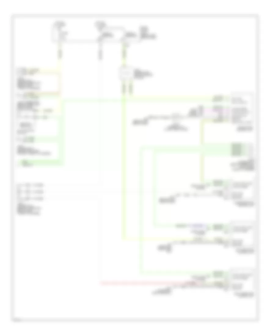
Anti-theft Wiring Diagram (1 of 2) for Infiniti Q45 2003
 https://portal-diagnostov.com/license.html
Automotive Electricians Portal FZCO
Automotive Electricians Portal FZCO
https://portal-diagnostov.com/license.html
https://portal-diagnostov.com/license.html
Automotive Electricians Portal FZCO
Automotive Electricians Portal FZCO
List of elements for Anti-theft Wiring Diagram (1 of 2) for Infiniti Q45 2003:
- (in engine room box)
- (on left front fenderwell, near engine oil level gauge)
- (under left front door sill)
- (under right front door sill)
- 13r
- 19r
- 20b
- 25r
- Accessory
- B17
- B17 (under left
- B217
- B57 (at center
- Battery
- Between full stroke & neutral
- Body control module (behind left kick panel)
- Data line a-3
- Door sw (as)
- Door sw (dr)
- Door sw (rr)
- E204
- E62
- Front door sill)
- Front door switch (driver side)
- Front door switch (passenger side)
- Fuse 10a
- Fuse 15a
- Fuse 20a
- Fuse block (j/b) 1 (behind left end of dash)
- Fuse, fusible link & relay block (j/b) (in engine room box)
- Fuse, fusible link & relay box
- Ground
- Head- lamp relay
- Headlamp rly
- Headlights system
- High horn
- Hood sw
- Hood switch (near hood lock stay)
- Horn chirp
- Horn relay
- Hot at all times
- Hot in acc or run
- Hot in on or start
- Ignition
- Joint connector 16 (behind upper right end of dash, taped to harness)
- Joint connector 25 (behind left kick panel, taped to harness)
- Joint connector 3 (behind upper left side of dash)
- Joint connector 37 (behind right rear shock tower, taped to harness)
- Joint connector 9 (behind center of dash)
- Keyless ground
- Keyless power
- Keyless sign
- Left rear door lock assembly (door switch)
- Low horn
- M24 (behind left side of dash)
- Pnk
- Rear of vehicle)
- Red
- Remote keyless entry receiver (at left "c" pillar)
- Right rear door lock assembly (door switch)
- Theft ind
- Trunk lid key cylinder switch (unlock switch)
- Trunk lid lock switch
- Trunk sw
- Trunk unlock sw
- Trunk, tailgate, fuel doors system
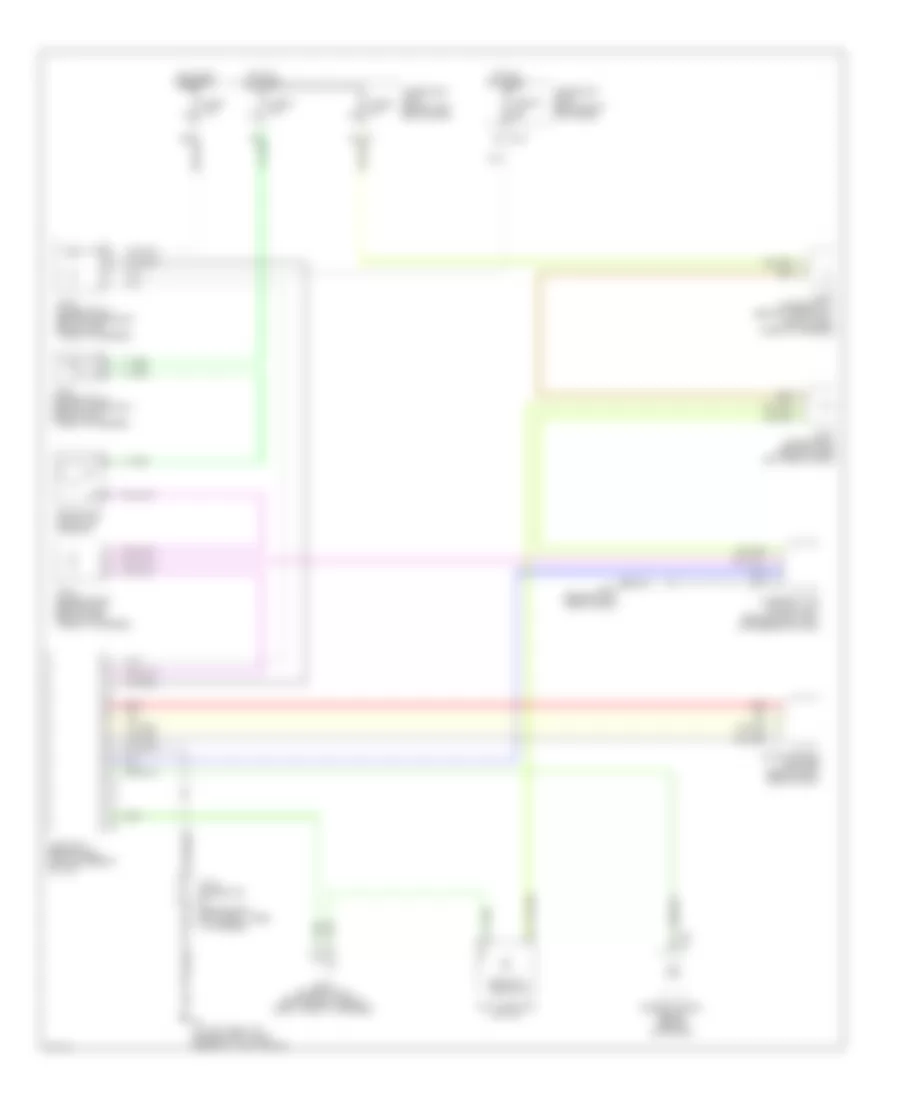
Anti-theft Wiring Diagram (2 of 2) for Infiniti Q45 2003
List of elements for Anti-theft Wiring Diagram (2 of 2) for Infiniti Q45 2003:
- B17 (under left front door sill)
- B217 (under right front door sill)
- Bat (c/b)
- Circuit breaker
- D38
- D39
- D58
- D59
- D78
- D79
- Data line a-3
- Door
- Door locks system
- Driver door control unit
- Fuse 10a
- Fuse block (j/b) 1 (behind left end of dash)
- Ground
- Hot at all times
- Joint connector 11 (behind upper right side of dash, taped to harness)
- Joint connector 15 (behind upper right end of dash, taped to harness)
- Joint connector 20 (behind right side of dash, taped to harness)
- Joint connector 21 (behind lower right end of dash, taped to harness)
- Joint connector 3 (behind upper left side of dash)
- Joint connector 41 (in left front door)
- Joint connector 6 (behind center of dash)
- Left rear door control unit
- Local data line
- Lock switch
- Locks
- M114 (behind right side of dash)
- M24 (behind left side of dash)
- Multifunction switch
- Passenger door control unit
- Right rear door control unit
- Security indicator
- System
- Unlock sens
- Unlock switch
Immobilizer Wiring Diagram (NATS) for Infiniti Q45 2003
List of elements for Immobilizer Wiring Diagram (NATS) for Infiniti Q45 2003:
- (behind right kick panel, taped to harness)
- 6c m1
- 6n m145
- Engine control module (behind glove box)
- F102
- F8 (at left front of engine compt, near engine oil level gauge)
- Fuse 1 10a
- Fuse 32 10a
- Fuse 6 10a
- Fuse 8 10a
- Fuse block (j/b) 1 (behind left end of dash)
- Fuse block (j/b) 2 (behind right kick panel)
- Hot at all times
- Hot in on or start
- Im lime
- Joint connector
- Joint connector 11 (behind upper right side of dash, taped to harness)
- Joint connector 15 (behind upper right end of dash, taped to harness)
- Joint connector 16 (behind upper right end of dash, taped to harness)
- Joint connector 20 (behind right side of dash, taped to harness)
- Joint connector 3 (behind upper left side of dash)
- Key switch & key lock solenoid
- M115 (behind right side of dash)
- Multi-function switch
- Nats antenna amplifier (behind right side of dash)
- Nats immu (behind dash, left of steering column)
- Red
- Security indicator
- Steering lock control unit (behind dash, right of steering column)

 Čeština
 Dansk
Dansk Deutsch
 Ελληνικά
 English
 Español
 Suomi
Suomi Français
 Français
 עברית
עברית Hrvatski
 Magyar
 Italiano
 日本語
日本語 한국어
한국어 Nederlands
 Polski
 Português
 Português
 Română
 Русский
 Slovenčina
 Slovenščina
 Svenska
 Türkçe
 中文 (中国)