ANTI-THEFT
Forced Entry Wiring Diagram for Mitsubishi Outlander XLS 2010
 https://portal-diagnostov.com/license.html
Automotive Electricians Portal FZCO
Automotive Electricians Portal FZCO
https://portal-diagnostov.com/license.html
https://portal-diagnostov.com/license.html
Automotive Electricians Portal FZCO
Automotive Electricians Portal FZCO
List of elements for Forced Entry Wiring Diagram for Mitsubishi Outlander XLS 2010:
- (behind left side of dash) joint connector (can1)
- (right rear of engine compt) g2
- A-03
- A-61
- C-301
- C-304
- C-311
- C-312
- C-313
- C-316
- C-317
- C-34
- Can drive circuit
- Can transceiver circuit
- Center panel unit
- Combination meter
- Computer data lines system
- Cpu
- D-12
- D-135
- Engine compartment relay box (left side of engine compt)
- Etacs-ecu (behind left side of dash)
- Exterior lights system
- Fuse 15a
- Fuse 4 10a
- Fuse 7.5a
- Fuse 9 20a
- G1 (right front of engine compt)
- G15 (left side of engine compt)
- G2 (right rear of engine compt)
- G6 (behind left side of dash)
- G7 (left front of roof)
- Hood switch (center front of engine compt)
- Horn relay
- Horns system
- Hot at all times
- Hot w/ ig1 relay energized
- Immobilizer antenna
- Interface circuit
- Keyless entry receiver
- Kos-ecu (w/ keyless entry) (behind left side of dash)
- Lcd (theft-alarm ind)
- Left front door switch (in left "b" pillar)
- Left rear door switch (in left "c" pillar)
- Liftgate switch (center of liftgate)
- Lin cut off control unit
- Nca
- Off
- Pnk
- Receiver antenna module (near ignition switch)
- Red
- Right front door switch (in right "b" pillar)
- Right rear door switch (in right "c" pillar)
- Theft alarm sensor (if equipped)
- Theft alarm siren (w/ theft alarm sensor)
- Theft-alarm horn (right rear corner of engine compt)
- Theft-alarm horn relay (w/o theft- alarm sensor) (in engine room relay box)
- Theft-alarm ind
- Tone alarm
- Turn-signal light control circuit
- Wireless control module (w/o keyless entry) (near ignition switch)
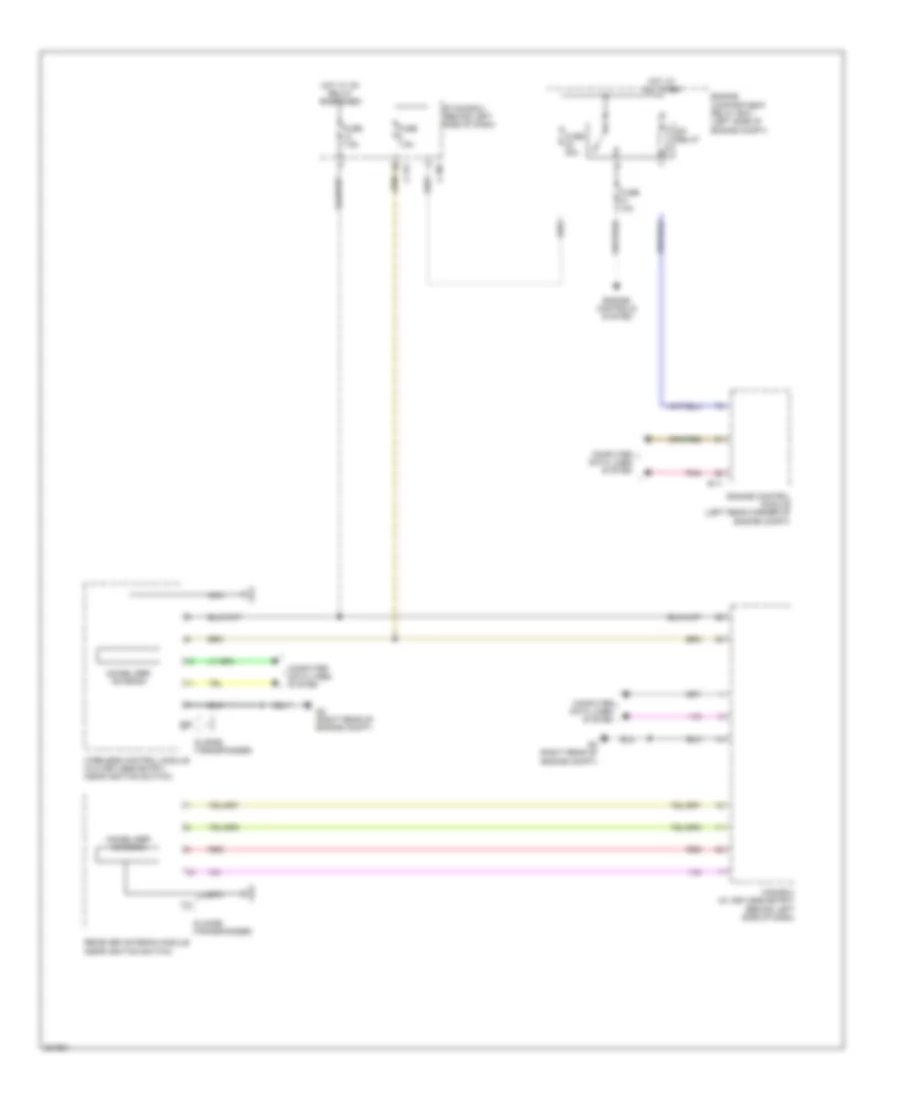
Immobilizer Wiring Diagram for Mitsubishi Outlander XLS 2010
List of elements for Immobilizer Wiring Diagram for Mitsubishi Outlander XLS 2010:
- B-11
- C-307
- C-317
- Computer data lines system
- Engine compartment relay box (left side of engine compt)
- Engine control module (left rear corner of engine compt)
- Engine controls system
- Etacs-ecu (behind left side of dash)
- Fuse 10a
- Fuse 30a
- Fuse 7.5a
- G2 (right rear of engine compt)
- Hot at all times
- Hot w/ ig1 relay energized
- Id code (transponder)
- Immobilizer antenna
- Kos-ecu (w/ keyless entry) (behind left side of dash)
- Mfi relay
- Nca
- Pnk
- Receiver antenna module (near ignition switch)
- Red
- Wireless control module (w/o keyless entry) (near ignition switch)

 Čeština
 Dansk
Dansk Deutsch
 Ελληνικά
 English
 Español
 Suomi
Suomi Français
 Français
 עברית
עברית Hrvatski
 Magyar
 Italiano
 日本語
日本語 한국어
한국어 Nederlands
 Polski
 Português
 Português
 Română
 Русский
 Slovenčina
 Slovenščina
 Svenska
 Türkçe
 中文 (中国)