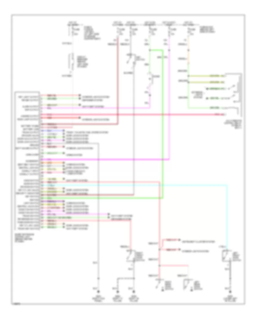
BODY COMPUTER
Body Computer Wiring Diagrams for Nissan Maxima GXE 2000
 https://portal-diagnostov.com/license.html
Automotive Electricians Portal FZCO
Automotive Electricians Portal FZCO
https://portal-diagnostov.com/license.html
https://portal-diagnostov.com/license.html
Automotive Electricians Portal FZCO
Automotive Electricians Portal FZCO
List of elements for Body Computer Wiring Diagrams for Nissan Maxima GXE 2000:
- 10h
- 12k
- 12l
- Accessory
- Alarm output
- Anti-theft system
- Batt saver output
- Battery (c/b)
- Battery (fuse)
- Central lock sw
- Central unlck sw
- Circuit breaker (behind left side of dash)
- Computer data lines system
- Condition switch
- Consult input
- Consult output
- Defogger system
- Diode
- Door lock output
- Door locks system
- Door switch
- Door unlk output
- Dr door switch
- Dr door unlck
- Exterior lights system
- Fuse & fusible link box (at left side of engine compartment)
- Fuse 10a
- Fuse block (behind left side of dash)
- Fuse i 40a
- G203 (right kick panel)
- G305 (right "b" pillar)
- G308 (lower left "b" pillar)
- G905 (right "c" pillar)
- Ground
- Hazard output
- Hood switch
- Horn chirp
- Horns system
- Hot at all times
- Hot in accy or on
- Hot in on or start
- Ignition
- Instrument cluster system
- Interior lights system
- Key cyl sw lock
- Key cyl sw unlck
- Key light output
- Key switch
- Left front door switch
- Left rear door switch
- Light switch
- Multi-remote control relay (in relay box 1)
- Pass door switch
- Pnk
- Rap output
- Red
- Right front door switch
- Right rear door switch
- Room lamp output
- Rr def output
- Rr defggr switch
- Seat belt switch
- Security indicator
- Smart entrance control unit (behind center of dash)
- Trunk key switch
- Trunk output
- Trunk switch
- Trunk, tailgate, fuel doors system
- Warning system
 Čeština
 Dansk
Dansk Deutsch
 Ελληνικά
 English
 English
 Español
 Suomi
Suomi Français
 Français
 עברית
עברית Hrvatski
 Magyar
 Italiano
 日本語
日本語 한국어
한국어 Nederlands
 Polski
 Português
 Português
 Română
 Русский
 Slovenčina
 Slovenščina
 Svenska
 Türkçe
 中文 (中国)
