BODY COMPUTER
Body Computer Wiring Diagrams for Volvo V40 2000
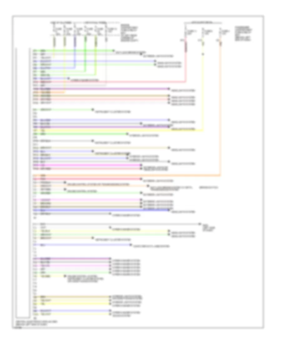
List of elements for Body Computer Wiring Diagrams for Volvo V40 2000:
- (brake switch)
- Anti-lock brake system
- Anti-lock brake system (w/ dstc), transmissions system
- C12
- Central electronic module (cem) (behind left end of dash)
- Computer data lines system
- Cruise control system
- Cruise control system or transmissions system
- Cruise control system, instrument cluster system, air conditioning system
- E13
- Engine compartment fuse & relay box (in left rear corner of engine compt)
- Exterior lights or headlights system
- Exterior lights system
- F10
- F11
- F12
- F13
- F14
- F15
- F16
- Fuse 10a
- Fuse 14 20a
- Fuse 15a
- Fuse 18 10a
- Fuse 20a
- Fuse 4 10a
- Fuse 6 15a
- G202 (left side of dash)
- Headlights system
- Hot at all times
- Hot in acc or on
- I22
- Instrument cluster system
- Interior lights system
- Interior lights system, air conditioning system
- N/a
- P10
- P11
- P12
- P13
- P14
- P15
- P16
- P17
- P18
- Passenger compartment fuse & relay box (behind left end of dash)
- Pnk
- Sound system
- Wiper/washer system
 Čeština
 Dansk
Dansk Deutsch
 Ελληνικά
 English
 Español
 Suomi
Suomi Français
 Français
 עברית
עברית Hrvatski
 Magyar
 Italiano
 日本語
日本語 한국어
한국어 Nederlands
 Polski
 Português
 Português
 Română
 Русский
 Slovenčina
 Slovenščina
 Svenska
 Türkçe
 中文 (中国)
 English