COMPUTER DATA LINES
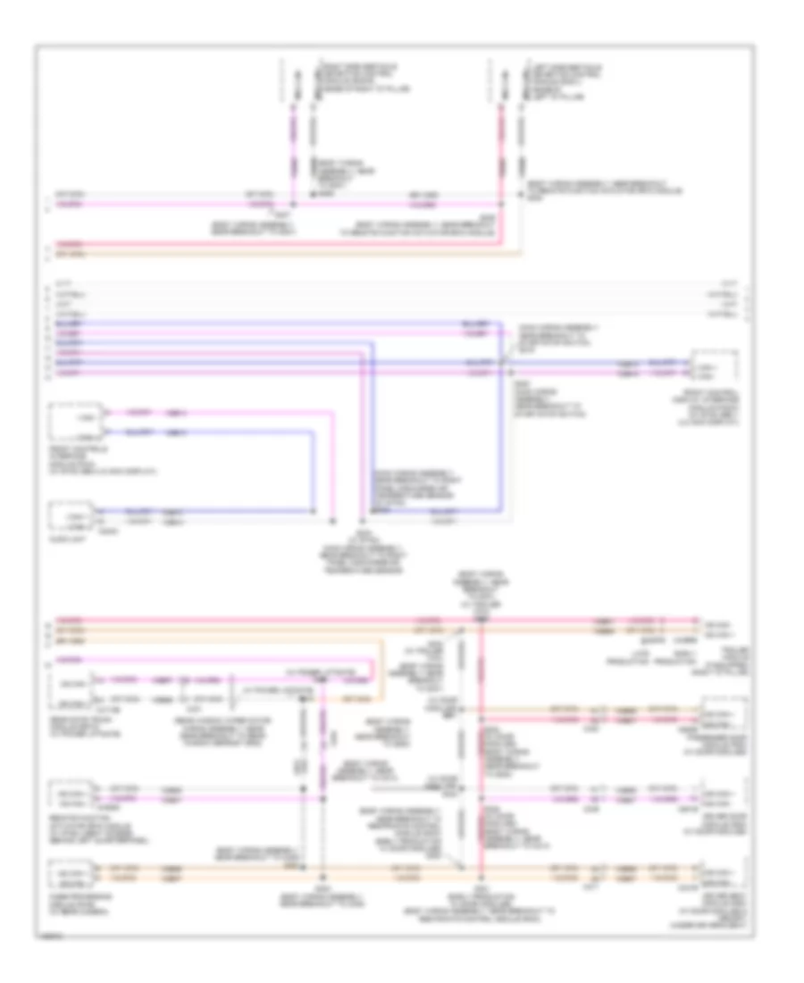
Computer Data Lines Wiring Diagram (1 of 3) for Ford Escape SE 2014
 https://portal-diagnostov.com/license.html
Automotive Electricians Portal FZCO
Automotive Electricians Portal FZCO
https://portal-diagnostov.com/license.html
https://portal-diagnostov.com/license.html
Automotive Electricians Portal FZCO
Automotive Electricians Portal FZCO
List of elements for Computer Data Lines Wiring Diagram (1 of 3) for Ford Escape SE 2014:
- (left front of luggage area) (w/ sony sound) audio digital signal processing (dsp) module
- (main wiring assembly, near breakout to
- (main wiring assembly, near breakout to electric booster heater)
- (main wiring assembly, near breakout to front passive start antenna) s212
- (main wiring assembly, near breakout to panel/floor mode door actuator)
- (main wiring assembly, near breakout to passenger air bag deactivation (pad) indicator) s222
- (main wiring assembly, near breakout to passive anti-theft transceiver)
- (w/ sony sound)
- (w/ sync gen 2 (8 display)) s226
- Accessory protocol interface module (apim) (under center console)
- Body control module (bcm) (bottom right center of dash)
- C210
- C214
- C2280a
- C2280b
- C2280c
- C2280f
- C228b
- C2357a
- C3053
- C4326a
- C934
- Data link connector (dlc) (lower left side of dash)
- Early production
- Electric booster heater)
- Electronic automatic temperature control (eatc) module (manual a/c)
- Fuse 5a
- G204 (left kick panel)
- Gd133
- Gd138
- Global positioning system module (gpsm) (w/ gps) (behind instrument cluster)
- Heating ventilation & air conditioning (hvac) control module (automatic a/c)
- Hot at all times
- Hs can +
- Hs can -
- I can +
- I can + ms can +
- I can -
- I can - ms can -
- Instrument panel cluster (ipc)
- Late production
- Micro
- Ms can +
- Ms can -
- Ms can+
- Ms can-
- Msx can +
- Msx can -
- S209
- S210 (main wiring assembly, in breakout to data link connector (dlc))
- S211
- S223 (main wiring assembly, near breakout to passenger air bag deactivation (pad) indicator)
- S224
- S225
- S227 (w/ sync gen 2 (8 inch display))
- S230
- S231 (w/ sync)
- S236 (steering wheel harness, near breakout to c260)
- S237
- S306 (w/ sony sound) (body wiring assembly, near breakout to c311)
- S307 (w/ sony sound) (body wiring assembly, near breakout to c311)
- Sbp26
- Termination msx can +
- Termination msx can -
- Vdb04
- Vdb05
- Vdb06
- Vdb07
- Vdb13
- Vdb14
- W/ sync gen 1 (4.2 inch display)
- W/ sync gen 2 (8 inch display)
- W/o sync
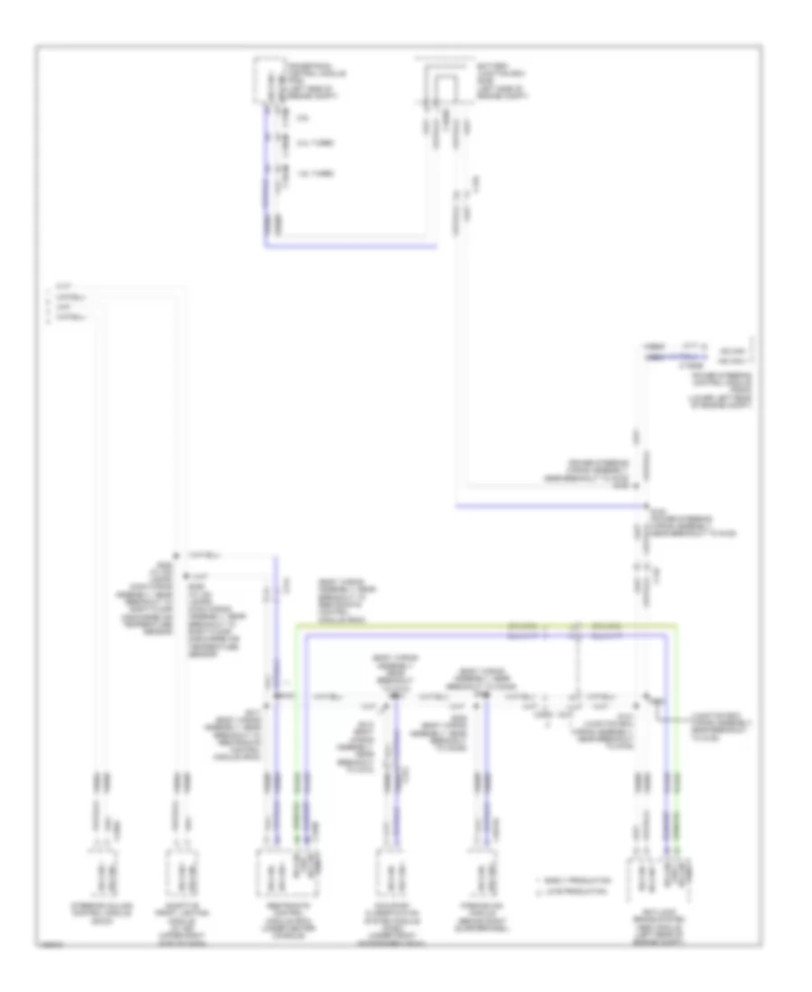
Computer Data Lines Wiring Diagram (2 of 3) for Ford Escape SE 2014
List of elements for Computer Data Lines Wiring Diagram (2 of 3) for Ford Escape SE 2014:
- (body wiring assembly, near breakout to c214)
- (body wiring assembly, near breakout to c405) s302
- (body wiring assembly, near breakout to g200)
- (body wiring assembly, near breakout to g301)
- (body wiring assembly, near breakout to g301) (w/ trailer tow) s405
- (body wiring assembly, near breakout to remote function actuator (rfa) module) s408
- (body wiring assembly, near breakout to restraints control module (rcm)) (early production w/ door modules) s320
- (main wiring assembly, near breakout to right panel discharge air temperature sensor) (w/ sync) s233
- (main wiring assembly, near breakout to start/stop switch) s219
- (rear window wiper motor wiring assembly, near near breakout to rear window defrost grid)
- (w/ door modules) s201
- (w/ door modules) s324
- (w/ power liftgate) s411
- (w/ power liftgate) s412
- Audio unit
- C240a
- C311
- C339
- C340
- C341b
- C4174b
- C431
- C4392d
- C4397b
- C501b
- C652b
- C934
- Driver door module (ddm) (w/ door modules)
- Driver seat module (dsm) (w/ door modules & memory) (under driver's seat)
- Early production
- Front control/ display interface module (fcdim) (w/ sync gen 1 (4.2 inch display))
- Front controls interface module (fcim) (w/ sync gen 2 (8 inch display))
- I can +
- I can -
- Image processing module (pm-b) (w/ rear camera)
- Late production
- Left side obstacle detection control module (sod-l) (base of left "d" pillar)
- Ms can +
- Ms can -
- Msx can +
- Msx can -
- Near breakout to g200)
- Passenger door module (pdm) (w/ door modules)
- Rear gate trunk module (rgtm) (w/ power liftgate)
- Remote function actuator (rfa) module (w/ intelligent access) (behind left quarterpanel)
- Right side obstacle detection control module (sod-r) (base of right "d" pillar)
- S220 (main wiring assembly, near breakout to start/stop switch)
- S234 (w/ sync) (main wiring assembly, near breakout to right panel discharge air temperature sensor)
- S303 (body wiring assembly, near breakout to c405)
- S321 (early production w/ door modules) (body wiring assembly, near breakout to restraints control module (rcm))
- S325 (w/ door modules) (body wiring assembly, near breakout to c214)
- S404 (w/ trailer tow) (body wiring assembly, near breakout to g301)
- S407
- S409 (body wiring assembly, near breakout to remote function actuator (rfa) module)
- Trailer module (if equipped) (right "d" pillar)
- Vdb06
- Vdb06 (body wiring assembly, near breakout to g301) s406
- Vdb07
- Vdb13
- Vdb14
Computer Data Lines Wiring Diagram (3 of 3) for Ford Escape SE 2014
List of elements for Computer Data Lines Wiring Diagram (3 of 3) for Ford Escape SE 2014:
- (body wiring assembly, near breakout to c3049) s308
- (body wiring assembly, near breakout to c312)
- (body wiring assembly, near breakout to restraints control module (rcm))
- (junction box wiring assembly, near breakout to g105)
- (power steering wiring assembly, near breakout to g108) s153
- 1.6l turbo
- 2.0l turbo
- 2.5l
- Adaptive front lighting module (w/ hid) (upper right side of dash)
- Anti-lock brake system (abs) module (left rear of engine compt)
- Battery junction box (bjb) (left side of engine compt)
- C1035c
- C133
- C1381b
- C1463b
- C1551b
- C175b
- C210
- C214
- C226a
- C3053
- C310b
- C312
- C4014a
- Early production
- Hs can +
- Hs can -
- Late production
- Near breakout to g108)
- Occupant classification system module (ocsm) (under front passenger's seat)
- Parking aid module (behind right quarterpanel)
- Power steering control module (pscm) (lower left rear of engine compt)
- Powertrain control module (pcm) (left side of engine compt)
- Restraints control module (rcm) (under center console)
- S141 (junction box wiring assembly, near breakout to g105)
- S142
- S228 (w/ hid lamps) (main wiring assembly, near breakout to right floor discharge air temperature sensor)
- S229 (w/ hid lamps) (main wiring assembly, near breakout to right floor discharge air temperature sensor)
- S309 (body wiring assembly, near breakout to c3049)
- S312
- S313 (body wiring assembly, near breakout to c312)
- S317 (body wiring assembly, near breakout to restraints control module (rcm))
- Steering column control module (sccm)
- Vca23
- Vca24
- Vdb04
- Vdb05
- Yaw + hs can
- Yaw - hs can

 Čeština
 Dansk
Dansk Deutsch
 Ελληνικά
 English
 Español
 Suomi
Suomi Français
 Français
 עברית
עברית Hrvatski
 Magyar
 Italiano
 日本語
日本語 한국어
한국어 Nederlands
 Polski
 Português
 Português
 Română
 Русский
 Slovenčina
 Slovenščina
 Svenska
 Türkçe
 中文 (中国)