COMPUTER DATA LINES
Computer Data Lines Wiring Diagram (1 of 3) for Ford Mustang 2010
 https://portal-diagnostov.com/license.html
Automotive Electricians Portal FZCO
Automotive Electricians Portal FZCO
https://portal-diagnostov.com/license.html
https://portal-diagnostov.com/license.html
Automotive Electricians Portal FZCO
Automotive Electricians Portal FZCO
List of elements for Computer Data Lines Wiring Diagram (1 of 3) for Ford Mustang 2010:
- (body main harness, near breakout to anti-lock brake system module)
- (body main harness, near breakout to passenger side scuff plate light)
- (main harness, near breakout to instrument panel)
- (main harness, near breakout to panel/ defrost mode door actuator)
- Accessory protocol interface module (apim) (w/ sync) (right side of dash)
- Anti-lock brake system (abs) module (left front of engine
- C175b
- C2041b restraints control module (under center console)
- Compt)
- Hs can +
- Hs can -
- Instrument cluster (ic)
- Occupant classification sensor module (ocsm) (under passenger's seat)
- Powertrain control module (pcm) (right front of engine compt)
- Rcs hs cna +
- Rcs hs cna -
- S132
- S133
- S207
- S208
- S238
- S239
- S257
- S308
- S309
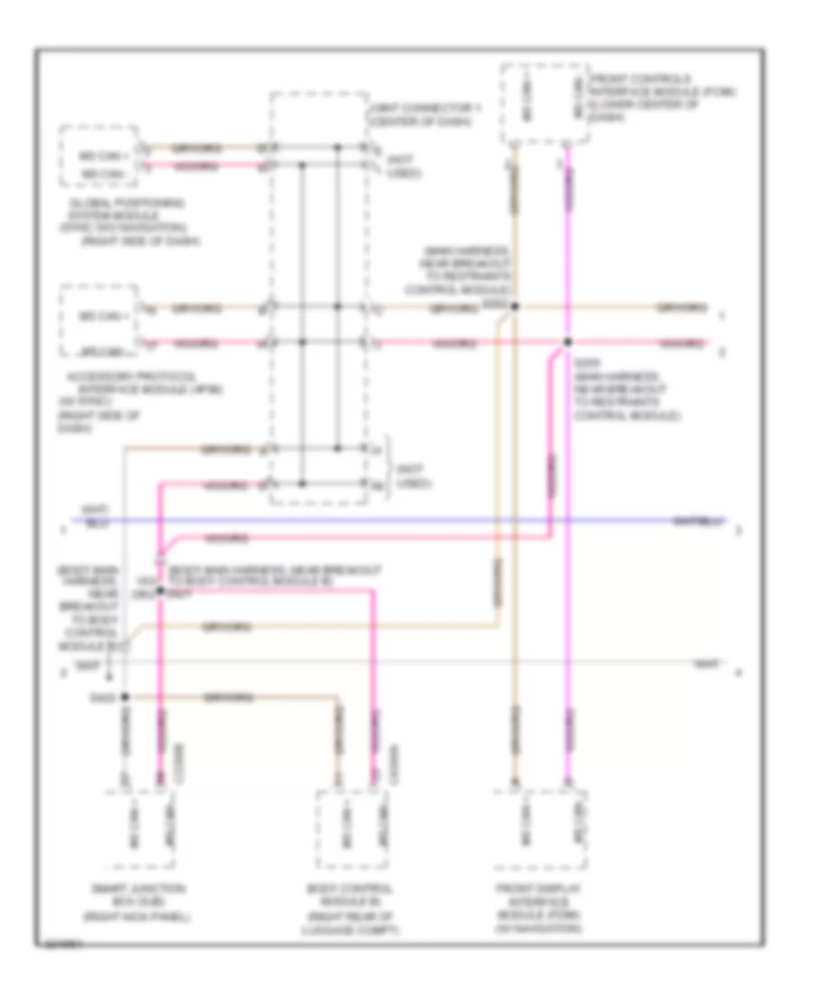
Computer Data Lines Wiring Diagram (2 of 3) for Ford Mustang 2010
List of elements for Computer Data Lines Wiring Diagram (2 of 3) for Ford Mustang 2010:
- (body main harness, near breakout to body control module b)
- (main harness, near breakout to restraints control module)
- (not used) m
- (right kick panel)
- (right rear of luggage compt)
- (right side of dash)
- (sync w/o navigation)
- (w/ sync) (right side of dash)
- Accessory protocol
- Body control module b)
- C2280b
- C4368a
- E (not l used)
- Front controls interface module (fcim) (lower center of dash)
- Front display interface module (fdim) (w/ navigation)
- Global positioning
- Interface module (apim)
- Joint connector 1 (center of dash)
- Ms can +
- Ms can -
- S255 (main harness, near breakout to restraints control module)
- S420
- Smart junction box (sjb)
- System module
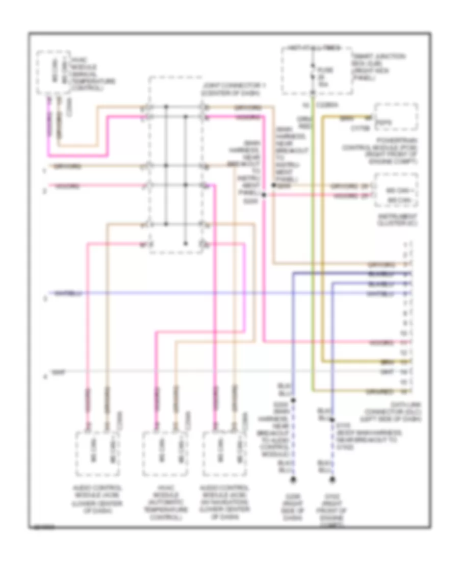
Computer Data Lines Wiring Diagram (3 of 3) for Ford Mustang 2010
List of elements for Computer Data Lines Wiring Diagram (3 of 3) for Ford Mustang 2010:
- (lower center of dash)
- (main harness, near breakout to instru- ment panel) s206
- (main harness, near breakout to audio control module)
- (main harness, near breakout to instru -ment panel)
- Audio control module (acm)
- Audio control module (acm) (w/ navigation) (lower center of dash)
- C175b
- C2280a
- C290a
- C290a ms can +
- C294a
- Data link connector (dlc) (left side of dash)
- Feps
- Fuse 15a
- G102 (right front of engine compt)
- G200 (right side of dash)
- Hot at all times
- Hvac module (manual temperature control)
- Hvac module (automatic temperature control)
- Instrument cluster (ic)
- Joint connector 1 (center of dash)
- Ms can +
- Ms can -
- Powertrain control module (pcm) (right front of engine compt)
- S115 (body main harness, near breakout to g102)
- S200
- S205
- Smart junction box (sjb) (right kick panel)

 Čeština
 Dansk
Dansk Deutsch
 Ελληνικά
 English
 Español
 Suomi
Suomi Français
 Français
 עברית
עברית Hrvatski
 Magyar
 Italiano
 日本語
日本語 한국어
한국어 Nederlands
 Polski
 Português
 Português
 Română
 Русский
 Slovenčina
 Slovenščina
 Svenska
 Türkçe
 中文 (中国)