Čeština
 Dansk
Dansk Deutsch
 Ελληνικά
 English
 Español
 Suomi
Suomi Français
 Français
 עברית
עברית Hrvatski
 Magyar
 Italiano
 日本語
日本語 한국어
한국어 Nederlands
 Polski
 Português
 Português
 Română
 Русский
 Slovenčina
 Slovenščina
 Svenska
 Türkçe
 中文 (中国)

COMPUTER DATA LINES
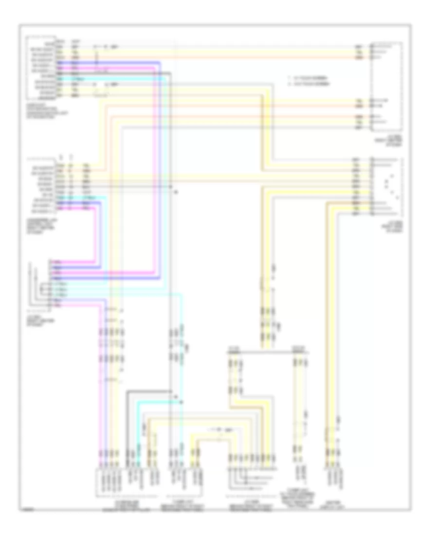
Data Link Connector Wiring Diagram (1 of 2) for Honda Odyssey EX 2014


List of elements for Data Link Connector Wiring Diagram (1 of 2) for Honda Odyssey EX 2014:
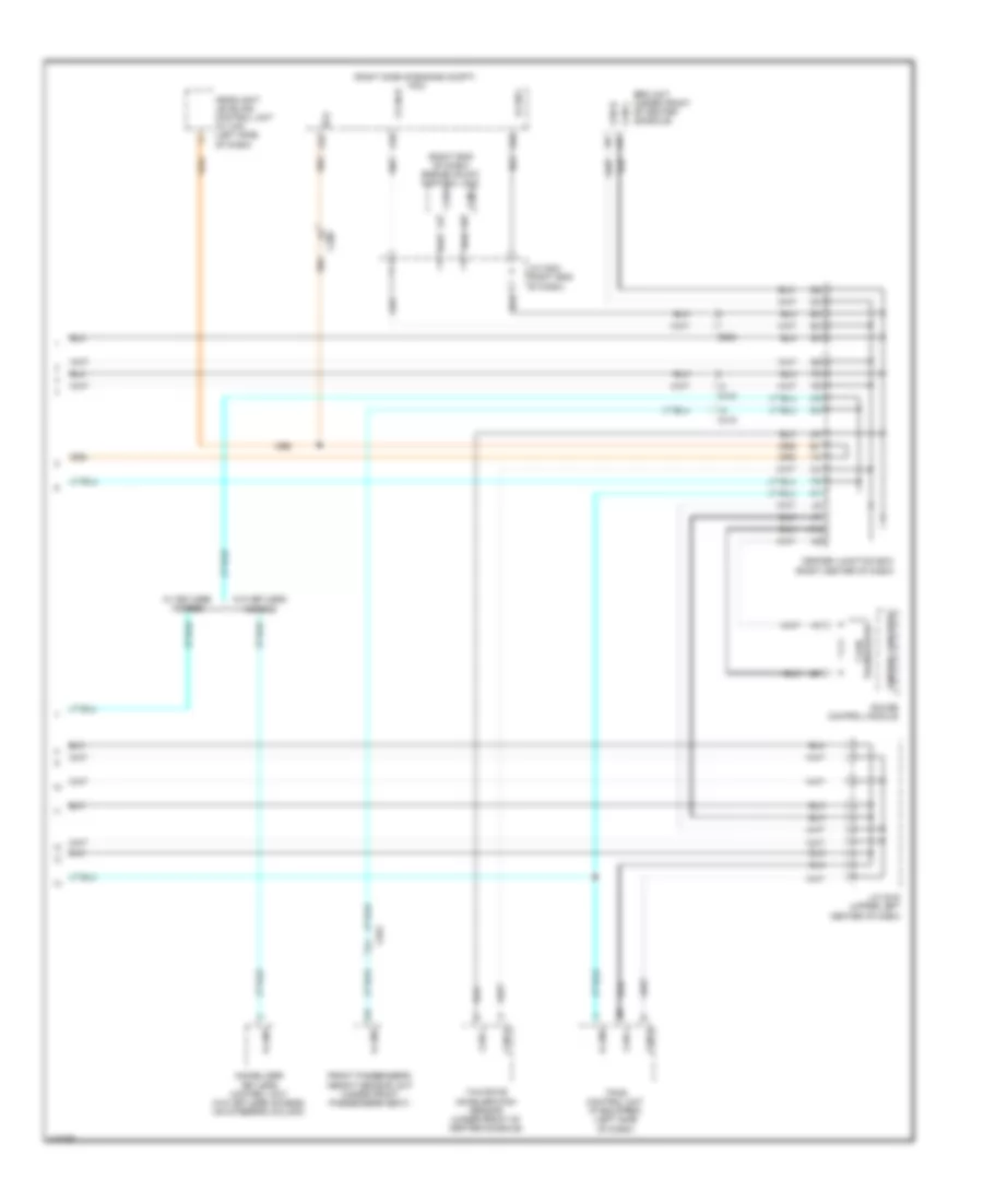
Data Link Connector Wiring Diagram (2 of 2) for Honda Odyssey EX 2014
List of elements for Data Link Connector Wiring Diagram (2 of 2) for Honda Odyssey EX 2014:
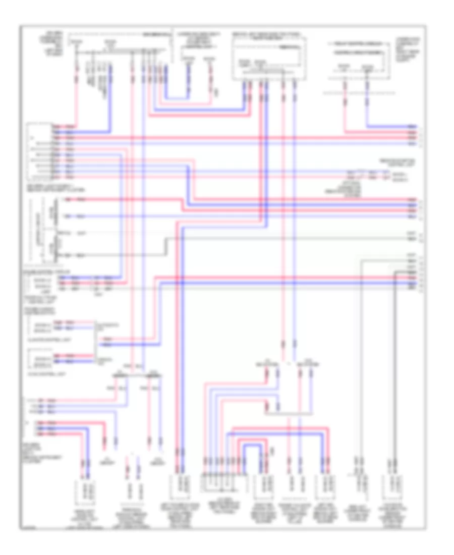
F-CAN & B-CAN Wiring Diagram (1 of 2) for Honda Odyssey EX 2014
List of elements for F-CAN & B-CAN Wiring Diagram (1 of 2) for Honda Odyssey EX 2014:
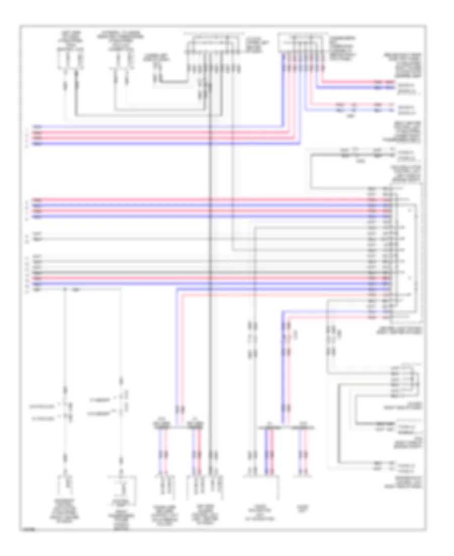
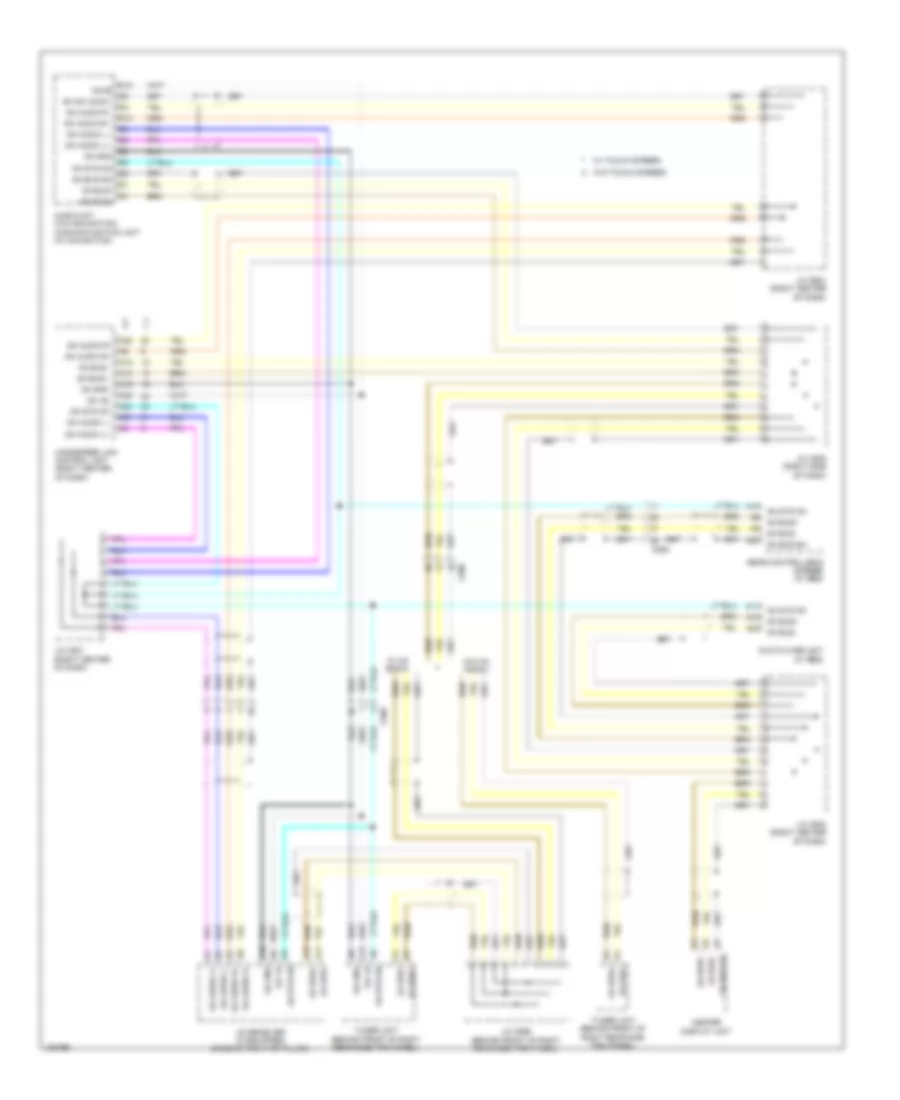
F-CAN & B-CAN Wiring Diagram (2 of 2) for Honda Odyssey EX 2014
List of elements for F-CAN & B-CAN Wiring Diagram (2 of 2) for Honda Odyssey EX 2014:
GA-NET Bus/GA-NET Audio Wiring Diagram, with RES for Honda Odyssey EX 2014
List of elements for GA-NET Bus/GA-NET Audio Wiring Diagram, with RES for Honda Odyssey EX 2014:
GA-NET Bus/GA-NET Audio Wiring Diagram, without RES for Honda Odyssey EX 2014
List of elements for GA-NET Bus/GA-NET Audio Wiring Diagram, without RES for Honda Odyssey EX 2014: