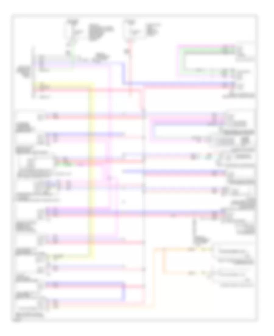
COMPUTER DATA LINES
Computer Data Lines Wiring Diagram for Infiniti FX35 2007
List of elements for Computer Data Lines Wiring Diagram for Infiniti FX35 2007:
- (behind instrument cluster) m45
- A/c & av switch
- A/t assembly (lower rear center of engine compt)
- Abs actuator & electric unit (control unit) (left rear of engine compt)
- Air bag diagnosis sensor unit (under rear of center console)
- Awd control unit (awd models) (behind right kick panel)
- B152
- Body control module (behind left kick panel)
- Bus +
- Bus -
- Bus shield
- Can-h
- Can-l
- Combination meter
- Cpu
- Data link connector (lower left side of dash)
- Ddl-rx
- Ddl-tx
- Diag-k
- Display control unit (behind right side of dash)
- Driver seat control unit
- Engine control module (ecm) (behind right end of dash)
- F502
- Front power seat (driver side)
- Front power window switch (passenger side)
- Fuse 19 10a
- Fuse 89 10a
- Fuse block (j/b) (behind left kick panel)
- Gnd can shield
- Hot at all times
- Hot in on or start
- Icc sensor (if equipped) (lower front of engine compt)
- Icc unit (if equipped) (right end of dash)
- Intelligent key unit (if equipped) (behind left end of dash)
- Ipdm e/r (intelligent power distribution module engine room) (right rear of engine compt)
- K-line
- Ldw camera unit (w/ ldw) (at top center of windshield)
- M55
- M72
- M76
- M88
- M89
- M90
- Nca
- Pnk
- Power window main switch
- Pwr wdo serial link
- Red
- Rx (comb meter)
- Shield
- Steering angle sensor (on steering column)
- Transmission control module
- Tx (comb meter)
- Unified meter & a/c amplifier (behind center console)
- Unified meter control unit
- Vdc/tcs/abs control unit
 Čeština
 Dansk
Dansk Deutsch
 Ελληνικά
 English
 English
 Español
 Français
 Français
 עברית
עברית Hrvatski
 Magyar
 Italiano
 日本語
日本語 한국어
한국어 Nederlands
 Polski
 Português
 Português
 Română
 Русский
 Slovenčina
 Slovenščina
 Svenska
 Türkçe
 中文 (中国)
 Suomi
Suomi