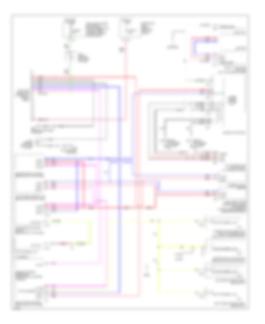
COMPUTER DATA LINES
Computer Data Lines Wiring Diagram for Infiniti G35 2003
List of elements for Computer Data Lines Wiring Diagram for Infiniti G35 2003:
- (behind instrument cluster) m30
- 2 door
- 4 door
- A/t assembly
- Air bag diagnosis sensor unit (under rear of center console)
- Audio unit
- Body control module (behind left kick panel)
- Bus +
- Bus -
- Can-h
- Can-l
- Combination meter
- Compass
- Cpu
- D36
- D55
- D75
- Data bit 1
- Data link connector (lower left side of dash)
- Diag-k
- Display & a/c auto amplifier (on top center of dash)
- Door
- Engine control module (behind right kick panel)
- F103
- F104
- F22 (on top front of engine)
- F307
- Fuse 19 10a
- Fuse 89 10a
- Fuse block (j/b) (behind left kick panel)
- Hot at all times
- Hot in on or start
- If equipped
- Intelligent power distribution module engine room (at eight rear corner of engine compartment)
- Intelligent power distribution module engine room (at right rear corner of engine compartment)
- J/c 2 (behind left side of dash)
- J/c 4 (behind right side of dash)
- K-line
- Left rear power window (sub-switch)
- M19
- M20
- M30 (behind instrument cluster)
- M31
- M39
- M59
- Navi control unit (w/ navigation) (in upper glove box)
- Nca
- Power window main switch (door lock & unlock switch)
- Power window sub-switch (front passenger side) (door lock & unlock switch)
- Pwr wdo serial link
- Red
- Right rear power window (sub-switch)
- Shield
- Shift control unit
- Speed sens
- Speed signal
- Steering angle sensor
- Transmission control module (behind right kick panel)
- Unified meter control unit
- Vdc/tcs/abs control unit (behind left side of dash)
 Čeština
 Dansk
Dansk Deutsch
 Ελληνικά
 English
 Español
 Suomi
Suomi Français
 Français
 עברית
עברית Hrvatski
 Magyar
 Italiano
 日本語
日本語 한국어
한국어 Nederlands
 Polski
 Português
 Português
 Română
 Русский
 Slovenčina
 Slovenščina
 Svenska
 Türkçe
 中文 (中国)
 English