
 Čeština
 Dansk
Dansk Deutsch
 Ελληνικά
 English
 English
 Español
 Suomi
Suomi Français
 Français
 עברית
עברית Hrvatski
 Magyar
 Italiano
 日本語
日本語 한국어
한국어 Polski
 Português
 Português
 Română
 Русский
 Slovenčina
 Slovenščina
 Svenska
 Türkçe
 中文 (中国)

COMPUTER DATA LINES
Computer Data Lines for Toyota Celica GT 2000
List of elements for Computer Data Lines for Toyota Celica GT 2000:
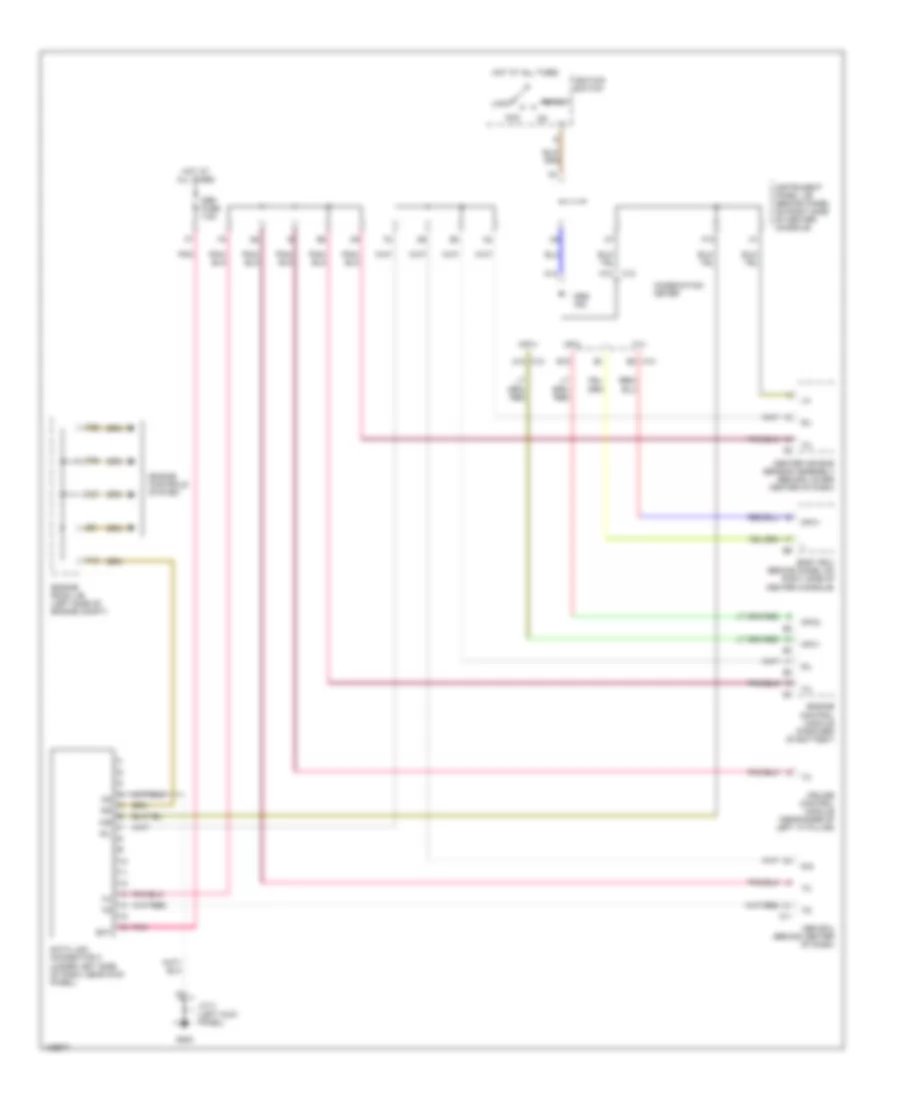

AIR CONDITIONINGBODY COMPUTERANTI-LOCK BRAKESCRUISE CONTROLCOOLING FANCOMPUTER DATA LINESDEFOGGERSHEADLIGHTSENGINE PERFORMANCEGROUND DISTRIBUTIONEXTERIOR LIGHTSHORNINSTRUMENT CLUSTERINTERIOR LIGHTSPASSIVE RESTRAINTSPOWER DISTRIBUTIONPOWER DOOR LOCKSPOWER TOP/SUNROOFPOWER MIRRORSPOWER WINDOWSRADIOSUPPLEMENTAL RESTRAINTSSTARTING/CHARGINGSHIFT INTERLOCKSWARNING SYSTEMSTRANSMISSIONWIPER/WASHER