COOLING FAN
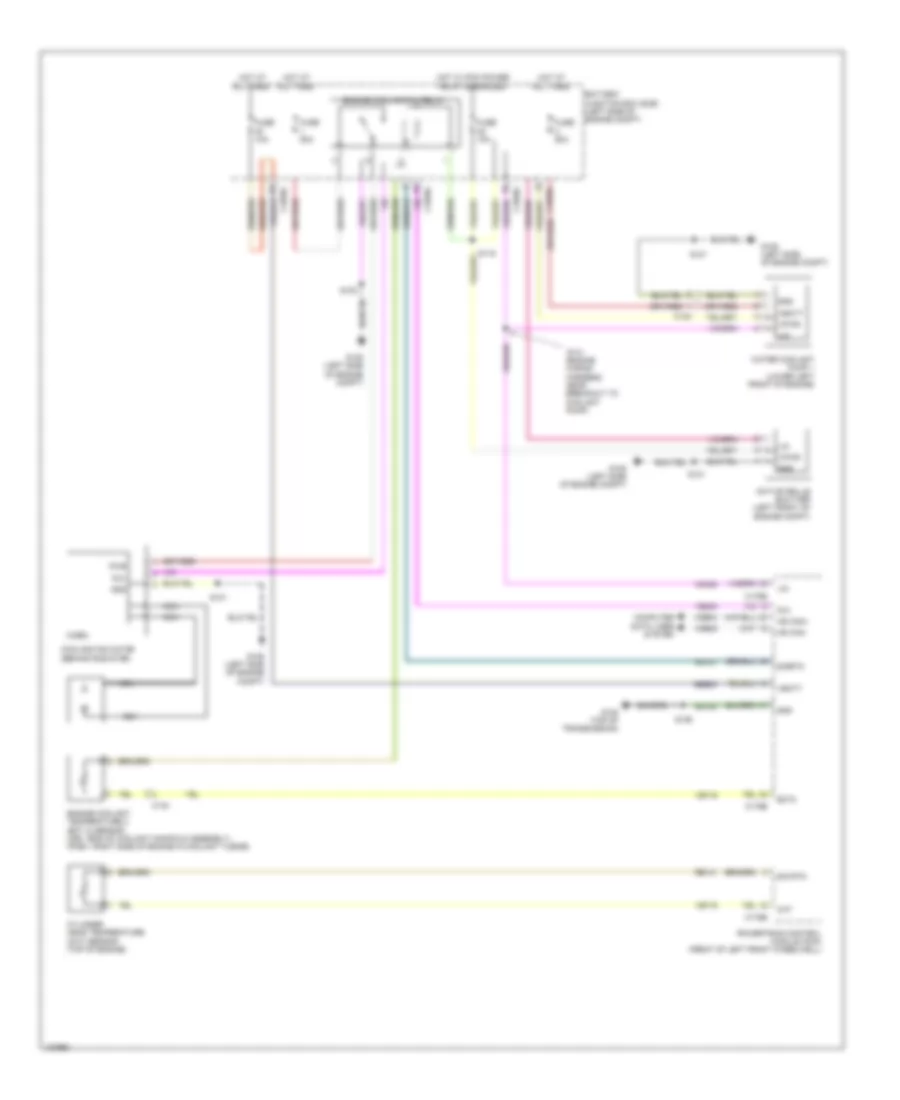
Cooling Fan Wiring Diagram for Ford C-Max Hybrid SE 2014
List of elements for Cooling Fan Wiring Diagram for Ford C-Max Hybrid SE 2014:
- (engine wiring harness, near breakout to coolant pump)
- Active grille shutter (left front of engine compt)
- Battery junction box (bjb) (left side of engine compt)
- C1035c
- C134
- C140
- C175b
- C175e
- Cht
- Computer data lines system
- Cooling fan motor (behind radiator)
- Cylinder head temperature (cht) sensor (top of engine)
- Ect2
- Engine coolant temperature 2 (ect 2) sensor (hev: end of coolant manifold assembly) (phev: right side of engine in coolant tubing)
- Engine cooling fan relay
- Fcv
- Fuse 10a
- Fuse 50a
- G105 (left side of engine compt)
- G108 (top of transmission)
- Gd120
- Gnd
- Hot at all times
- Hot w/ pcm power relay energized
- Hs can+
- Hs can-
- Lin
- Micro
- Nca
- Powertrain control module (pcm) (front of left front wheelwell)
- Pwr
- Re141
- Rh107
- S101
- S102
- S119
- S126
- S131
- Sbb30
- Sig rtn
- Sigrtn
- Vbatt
- Vdb04
- Vdb05
- Vdn08
- Ve203
- Ve716
- Vpwr
- Water coolant pump 1 (lower left front of engine)
 Čeština
 Dansk
Dansk Deutsch
 Ελληνικά
 English
 Español
 Suomi
Suomi Français
 Français
 עברית
עברית Hrvatski
 Magyar
 Italiano
 日本語
日本語 한국어
한국어 Nederlands
 Polski
 Português
 Português
 Română
 Русский
 Slovenčina
 Slovenščina
 Svenska
 Türkçe
 中文 (中国)
 English