COOLING FAN
4.0L
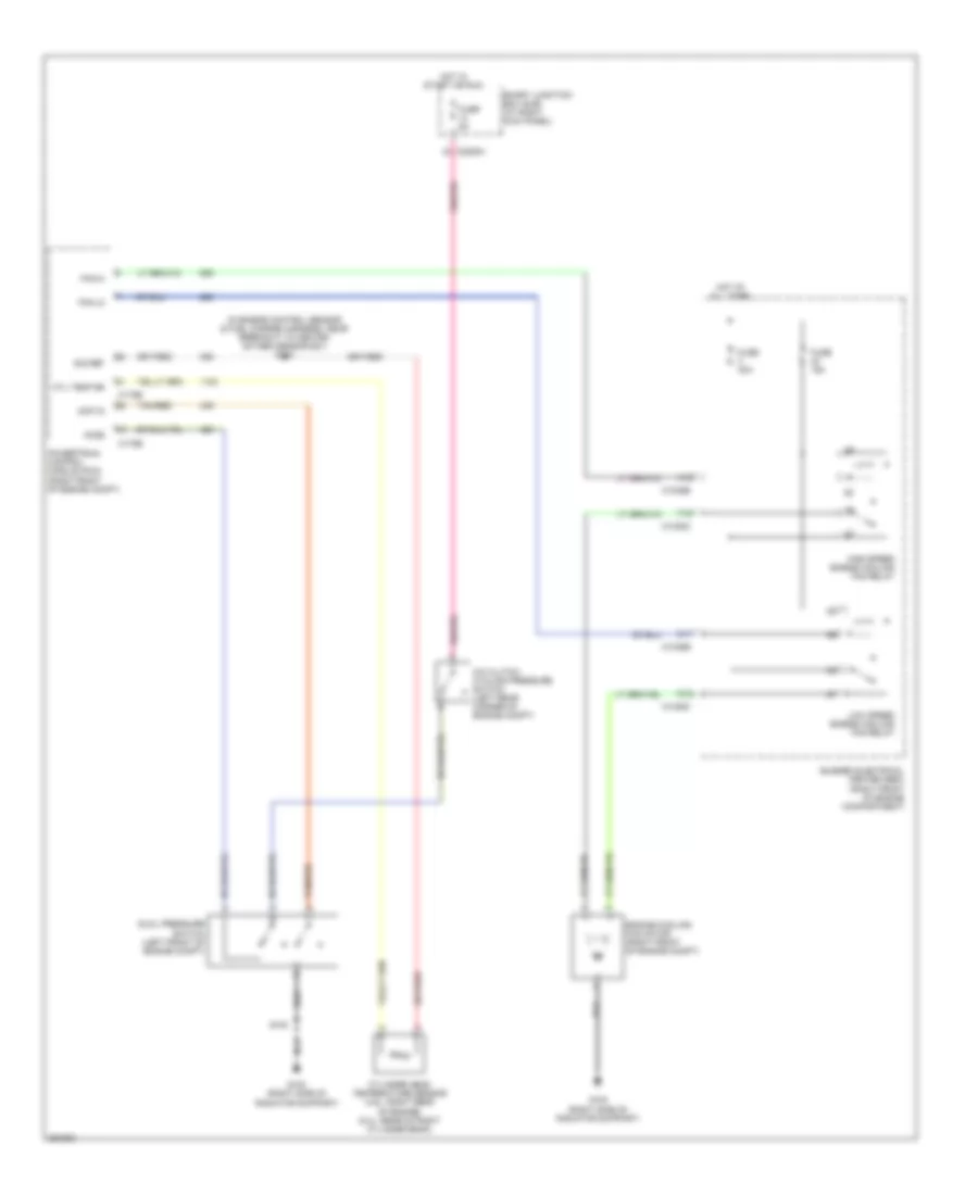
4.0L, Cooling Fan Wiring Diagram for Ford Mustang Shelby GT500 2007
 https://portal-diagnostov.com/license.html
Automotive Electricians Portal FZCO
Automotive Electricians Portal FZCO
https://portal-diagnostov.com/license.html
https://portal-diagnostov.com/license.html
Automotive Electricians Portal FZCO
Automotive Electricians Portal FZCO
List of elements for 4.0L, Cooling Fan Wiring Diagram for Ford Mustang Shelby GT500 2007:
- (in engine control sensor & fuel charge harness, on top of engine) s103
- A/c clutch cycling pressure switch (left rear corner of engine compt)
- A/c pressure transducer sensor (left front of engine compt)
- A12
- Accs
- Bussed electrical center (bec) (right front of engine compartment)
- C1035b
- C1035c
- C11
- C12
- C175b
- C175e
- C2280h
- Ect sig
- Engine coolant temperature sensor (on top front of engine)
- Engine cooling fan motor (right front of engine compt)
- F12
- Fan hi
- Fan lo
- Fuse 15a
- Fuse 40a
- Fuse 5a
- G100 (right side of radiator support)
- High speed engine cooling fan relay
- Hot at all times
- Hot in start or run
- Low speed engine cooling fan relay
- Powertrain control module (pcm) (right front of engine compt)
- Ref volt
- S102 (in engine control sensor & fuel charge harness, near breakout to egr system module)
- Sig ret
- Smart junction box (sjb) (at right kick panel)
- Sw sig
- Tan/red
4.6L
4.6L, Cooling Fan Wiring Diagram for Ford Mustang Shelby GT500 2007
List of elements for 4.6L, Cooling Fan Wiring Diagram for Ford Mustang Shelby GT500 2007:
- (in engine control sensor & fuel charge harness, near breakout to heated oxygen sensor #21) s102
- A/c clutch cycling pressure switch (left rear corner of engine compt)
- A12
- Accs
- Acp v8
- Bussed electrical center (bec) (right front of engine compartment)
- C1035b
- C1035c
- C11
- C12
- C175b
- C175e
- C2280h
- Cyl temp sn
- Cylinder head temperature sensor (4.6l: right rear of engine) (5.4l: rear of right cylinder bank)
- Dual pressure switch (left front of engine compt)
- Engine cooling fan motor (right front of engine compt)
- F12
- Fan hi
- Fan lo
- Fuse 15a
- Fuse 40a
- Fuse 5a
- G100 (right side of radiator support)
- High speed engine cooling fan relay
- Hot at all times
- Hot in start or run
- Low speed engine cooling fan relay
- Powertrain control module (pcm) (right front of engine compt)
- S100
- Sig ret
- Smart junction box (sjb) (at right kick panel)
- Tan/red
5.4L SUPERCHARGED
5.4L Supercharged, Cooling Fan Wiring Diagram for Ford Mustang Shelby GT500 2007
List of elements for 5.4L Supercharged, Cooling Fan Wiring Diagram for Ford Mustang Shelby GT500 2007:
- (in engine control sensor & fuel charge harness, near breakout to heated oxygen sensor #21) s102
- A/c clutch cycling pressure switch (left rear corner of engine compt)
- A12
- Accs
- Acp v8
- Bussed electrical center (bec) (right front of engine compartment)
- C1035b
- C1035c
- C11
- C12
- C175b
- C175e
- C2280h
- Cyl temp sn
- Cylinder head temperature sensor (4.6l: right rear of engine) (5.4l: rear of right cylinder bank)
- Dual pressure switch (left front of engine compt)
- Engine cooling fan motor (right front of engine compt)
- F12
- Fan hi
- Fan lo
- Fuse 15a
- Fuse 40a
- Fuse 5a
- G100 (right side of radiator support)
- High speed engine cooling fan relay
- Hot at all times
- Hot in start or run
- Low speed engine cooling fan relay
- Powertrain control module (pcm) (right front of engine compt)
- S100
- Sig ret
- Smart junction box (sjb) (at right kick panel)
- Tan/red

 Čeština
 Dansk
Dansk Deutsch
 Ελληνικά
 English
 Español
 Suomi
Suomi Français
 Français
 עברית
עברית Hrvatski
 Magyar
 Italiano
 日本語
日本語 한국어
한국어 Nederlands
 Polski
 Português
 Português
 Română
 Русский
 Slovenčina
 Slovenščina
 Svenska
 Türkçe
 中文 (中国)