COOLING FAN
Cooling Fan Wiring Diagram (1 of 2) for Lincoln MKS EcoBoost 2014
 https://portal-diagnostov.com/license.html
Automotive Electricians Portal FZCO
Automotive Electricians Portal FZCO
https://portal-diagnostov.com/license.html
https://portal-diagnostov.com/license.html
Automotive Electricians Portal FZCO
Automotive Electricians Portal FZCO
List of elements for Cooling Fan Wiring Diagram (1 of 2) for Lincoln MKS EcoBoost 2014:
- (behind center of front fascia) (3.7l) active grille shutter (ags)
- 3.5l
- 3.7l
- Battery junction box (bjb) (left side of engine compt)
- C1381b
- C1381e
- C175b
- C175e
- Cbb69
- Cec07
- Cec08
- Cht
- Computer data lines system
- Fuse 15a
- Fuse 20a
- Fuse 40a
- G100 (right side of engine compt)
- G102 (right rear of engine compt)
- Gd113
- Gnd
- Hfc
- Hot at all times
- Hot w/ pcm power relay energized
- Hs can +
- Hs can -
- Lfc
- Lin
- Powertrain control module (pcm) (right rear of engine compt)
- Pwr
- Pwr gnd
- Re405
- S116
- S122
- S159
- Sig rtn
- Vdb04
- Vdb05
- Vdn06
- Ve712
- Vpwr
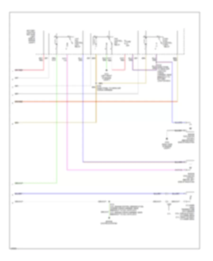
Cooling Fan Wiring Diagram (2 of 2) for Lincoln MKS EcoBoost 2014
List of elements for Cooling Fan Wiring Diagram (2 of 2) for Lincoln MKS EcoBoost 2014:
- 3.7l
- Battery junction box (bjb) (left side of engine compt)
- C192
- Cylinder head temperature (cht) sensor (3.5l: middle of right cylinder head) (3.7l: front of right cylinder head)
- Engine controls system
- Engine cooling fan motor 1 (behind left side of radiator)
- Engine cooling fan motor 2 (behind right side of radiator)
- Fan control (fc) relay
- Fuse 25a
- G100 (right side of engine compt)
- G101 (left front of engine compt)
- High fan control (hfc) relay
- Low fan control (lfc) relay

 Čeština
 Dansk
Dansk Deutsch
 Ελληνικά
 English
 Español
 Suomi
Suomi Français
 Français
 עברית
עברית Hrvatski
 Magyar
 Italiano
 日本語
日本語 한국어
한국어 Nederlands
 Polski
 Português
 Português
 Română
 Русский
 Slovenčina
 Slovenščina
 Svenska
 Türkçe
 中文 (中国)