COOLING FAN
Cooling Fan Wiring Diagram for Nissan Maxima GXE 1998
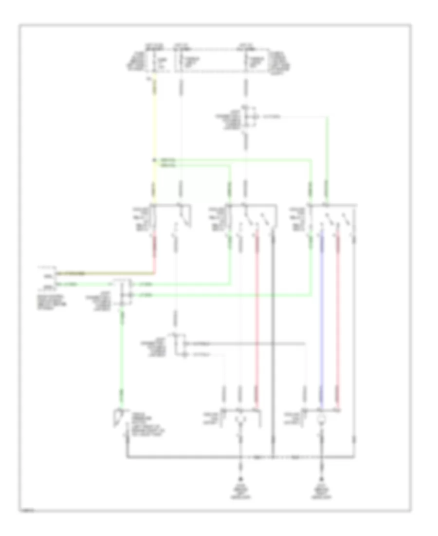
List of elements for Cooling Fan Wiring Diagram for Nissan Maxima GXE 1998:
- Cooling fan motor 1
- Cooling fan motor 2
- Cooling fan relay 1 (in relay box 2)
- Cooling fan relay 2 (in relay box 2)
- Cooling fan relay 3 (in relay box 2)
- Eccs control module (ecm) (below center of dash)
- Fuse & fusible link box (left side of engine compt)
- Fuse 10a
- Fuse block (behind left side of dash)
- Fusible link d 30a
- Fusible link e 30a
- G106 (behind left headlamp)
- G107 (behind right headlamp)
- Hot at all times
- Hot in on or start
- Joint connector 1 (in fuse & fusible link box)
- Joint connector 2 (in fuse & fusible link box)
- Joint connector 3 (in fuse & fusible link box)
- Rfrh
- Rfrl
- Triple pressure switch (left front of engine compt, on a/c liquid tank)
 Čeština
 Dansk
Dansk Deutsch
 Ελληνικά
 English
 English
 Español
 Suomi
Suomi Français
 Français
 עברית
עברית Hrvatski
 Magyar
 Italiano
 日本語
日本語 한국어
한국어 Nederlands
 Polski
 Português
 Português
 Română
 Slovenčina
 Slovenščina
 Svenska
 Türkçe
 中文 (中国)
 Русский