COOLING FAN
1.9L
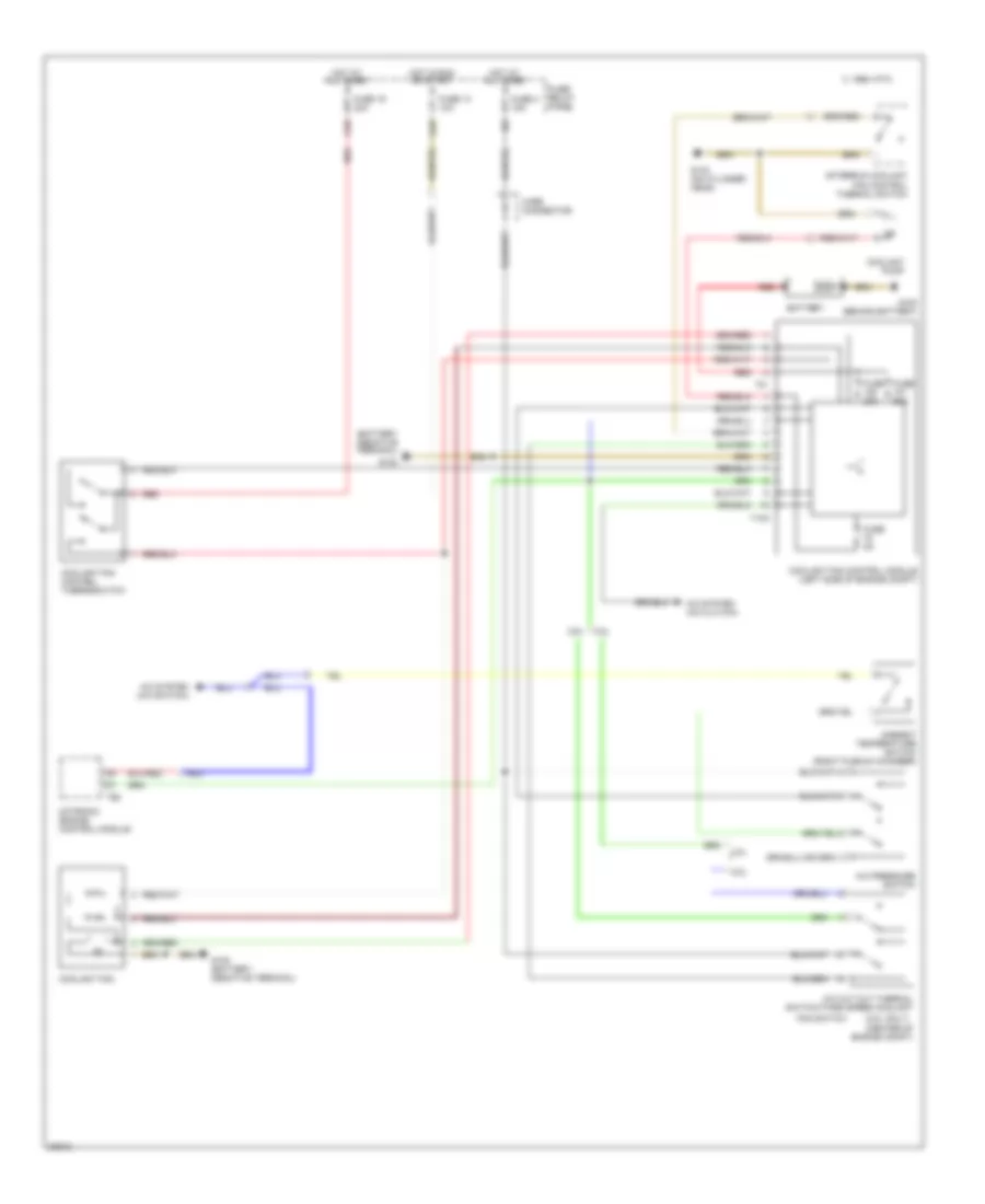
1.9L Turbo Diesel, Cooling Fan Wiring Diagram for Volkswagen Passat TDI 1996
 https://portal-diagnostov.com/license.html
Automotive Electricians Portal FZCO
Automotive Electricians Portal FZCO
https://portal-diagnostov.com/license.html
https://portal-diagnostov.com/license.html
Automotive Electricians Portal FZCO
Automotive Electricians Portal FZCO
List of elements for 1.9L Turbo Diesel, Cooling Fan Wiring Diagram for Volkswagen Passat TDI 1996:
- A/c pressure switch
- A/c system
- A1/5
- A1/7
- All times
- Battery
- Coolant fan
- Coolant fan control module (left side of engine compt)
- Coolant fan control thermoswitch
- D/3
- Fuse 10a
- Fuse 15a
- Fuse 30a
- Fuse 20a
- Fuse 50a
- Fuse/ relay panel
- G100 (behind battery)
- G132 (on engine block)
- Horns system
- Hot at
- Hot at all times
- Hot in run or start
- Red
- T10a
- T41
- Wire con- nector
2.0L
2.0L, Cooling Fan Wiring Diagram for Volkswagen Passat TDI 1996
List of elements for 2.0L, Cooling Fan Wiring Diagram for Volkswagen Passat TDI 1996:
- (2.8l only)
- (center of engine compt)
- 1995 vftc c
- 2.0l
- 2.8l
- A/c cut out thermal switch/third speed coolant
- A/c pressure switch
- A/c system (a/c clutch)
- A/c system (a/c switch)
- A1/5
- A1/7
- Afterrun coolant fan control thermal switch
- Ambient temperature switch (right plenum chamber)
- Battery
- Coolant fan
- Coolant fan control module (left side of engine compt)
- Coolant fan control thermoswitch
- Coolant pump
- D/3
- Fan switch
- Fuse 13 10a
- Fuse 19 30a
- Fuse 20a
- Fuse 4 15a
- Fuse 50a
- Fuse 5a
- Fuse/ relay panel
- G100
- G100 (behind battery)
- G133 (on cylinder head)
- Hot at all times
- Hot in run or start
- Motronic engine control module
- Red
- T10a
- T41
- T68
- Wire connector
2.8L
2.8L, Cooling Fan Wiring Diagram for Volkswagen Passat TDI 1996
List of elements for 2.8L, Cooling Fan Wiring Diagram for Volkswagen Passat TDI 1996:
- (2.8l only)
- (center of engine compt)
- 1995 vftc c
- 2.0l
- 2.8l
- A/c cut out thermal switch/third speed coolant
- A/c pressure switch
- A/c system (a/c clutch)
- A/c system (a/c switch)
- A1/5
- A1/7
- Afterrun coolant fan control thermal switch
- Ambient temperature switch (right plenum chamber)
- Battery
- Coolant fan
- Coolant fan control module (left side of engine compt)
- Coolant fan control thermoswitch
- Coolant pump
- D/3
- Fan switch
- Fuse 13 10a
- Fuse 19 30a
- Fuse 20a
- Fuse 4 15a
- Fuse 50a
- Fuse 5a
- Fuse/ relay panel
- G100
- G100 (behind battery)
- G133 (on cylinder head)
- Hot at all times
- Hot in run or start
- Motronic engine control module
- Red
- T10a
- T41
- T68
- Wire connector

 Čeština
 Dansk
Dansk Deutsch
 Ελληνικά
 English
 Español
 Suomi
Suomi Français
 Français
 עברית
עברית Hrvatski
 Magyar
 Italiano
 日本語
日本語 한국어
한국어 Nederlands
 Polski
 Português
 Português
 Română
 Русский
 Slovenčina
 Slovenščina
 Svenska
 Türkçe
 中文 (中国)