
 Čeština
 Dansk
Dansk Deutsch
 Ελληνικά
 English
 Español
 Suomi
Suomi Français
 Français
 עברית
עברית Hrvatski
 Magyar
 Italiano
 日本語
日本語 한국어
한국어 Nederlands
 Polski
 Português
 Português
 Română
 Русский
 Slovenčina
 Slovenščina
 Svenska
 Türkçe
 中文 (中国)

COOLING FAN
Cooling Fan Wiring Diagram for Volvo XC90 R-Design 2013
List of elements for Cooling Fan Wiring Diagram for Volvo XC90 R-Design 2013:
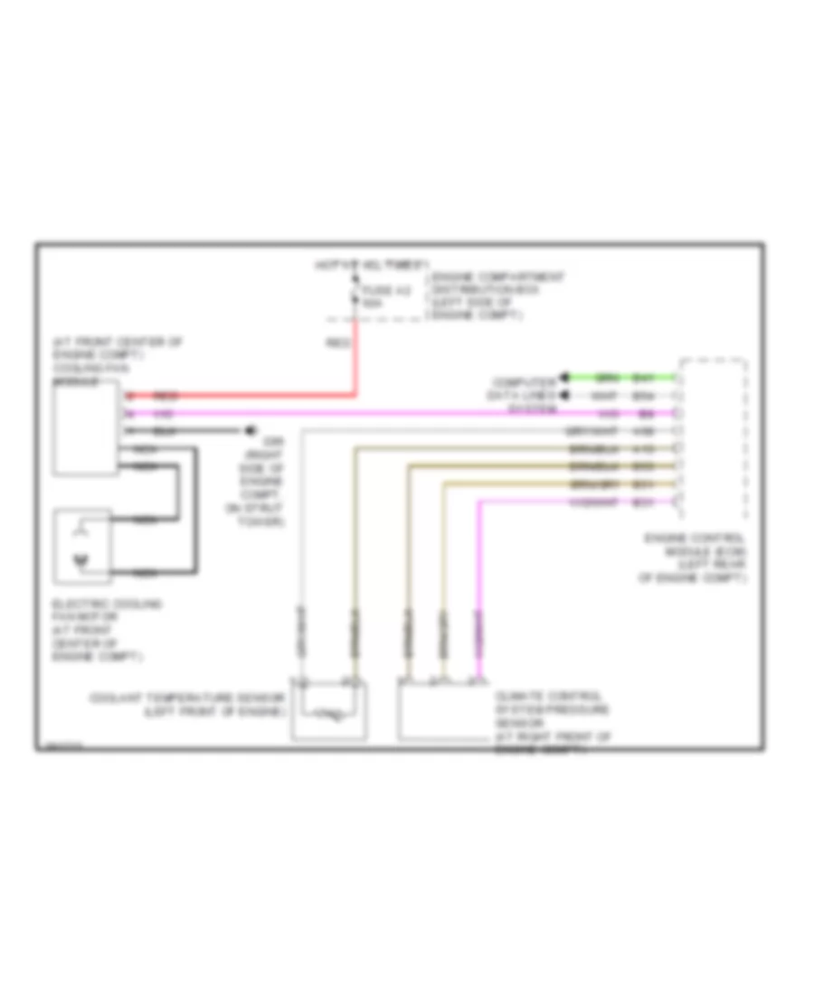

AIR CONDITIONINGCOMPUTER DATA LINESCOOLING FANBODY CONTROL MODULESCRUISE CONTROLDEFOGGERSENGINE PERFORMANCEELECTRONIC POWER STEERINGEXTERIOR LIGHTSHORNINSTRUMENT CLUSTERNAVIGATIONGROUND DISTRIBUTIONHEADLIGHTSPOWER DISTRIBUTIONPOWER DOOR LOCKSPOWER WINDOWSPOWER SEATSMEMORY SYSTEMSPOWER TOP/SUNROOFINTERIOR LIGHTSSHIFT INTERLOCKSUPPLEMENTAL RESTRAINTSTRANSMISSIONWARNING SYSTEMSRADIOSTARTING/CHARGINGWIPER/WASHERANTI-THEFTANTI-LOCK BRAKES