CRUISE CONTROL
Cruise Control Wiring Diagram for Chevrolet Tracker 1998
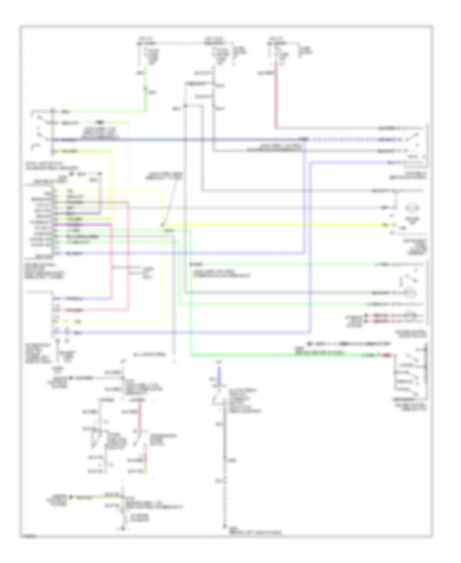
List of elements for Cruise Control Wiring Diagram for Chevrolet Tracker 1998:
- (4-spd a/t)
- (except 4-spd a/t)
- (main harn, 4 cm from stop lamp switch breakout)
- (main harn, 5cm from steering column breakout)
- (main harn, 7 cm from blower switch breakout)
- (main harn, near breakout to pcm)
- 3-speed
- 4-spd a/t only
- 4-speed
- A/t
- All times
- And start
- Brake sig
- Cancel
- Cancel sig
- Clutch pedal position interrupt switch (on clutch pedal support)
- Cruise control actuator (right engine compt, near strut tower)
- Cruise control mode switch
- Cruise control on/off switch
- Cruise ind
- Engine controls system
- Fi fuse 15a
- Fuse block
- G202 (behind left side of dash)
- G206 (behind center of dash)
- G206 (center of dash)
- Ground
- Hot at
- Hot in on
- Ig coil meter fuse 15a
- Ignition
- Ind ctrl
- Instrument panel cluster assembly
- Interior lights system
- Interrupt
- M/t
- Main relay (behind glove box)
- Mode sig
- O/d cut
- On/off ind
- Park/ neutral position switch
- Powertrain control module (under left side of dash)
- Red
- Res/acc
- S100 (main harn, 21 cm from wiper motor breakout)
- S136 (engine harn, 1 cm from distributor breakout)
- S204
- S210
- S215
- S222
- S251
- S252
- S260
- S272
- S284
- S295
- S298
- Set/coast
- Starter solenoid
- Stop lamp switch (on brake pedal bracket)
- Stop/ horn fuse 15a
- Tp input
- Transmission range switch
- Vss
 Čeština
 Dansk
Dansk Deutsch
 Ελληνικά
 English
 Español
 Suomi
Suomi Français
 Français
 עברית
עברית Hrvatski
 Magyar
 Italiano
 日本語
日本語 한국어
한국어 Nederlands
 Polski
 Português
 Português
 Română
 Русский
 Slovenčina
 Slovenščina
 Svenska
 Türkçe
 中文 (中国)
 English