CRUISE CONTROL
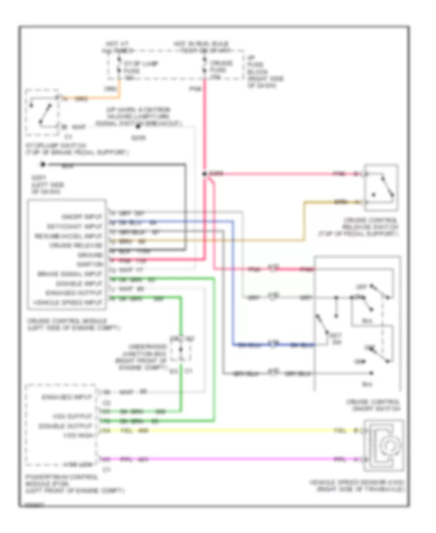
Cruise Control Wiring Diagram for Chevrolet Venture 2004
List of elements for Cruise Control Wiring Diagram for Chevrolet Venture 2004:
- (i/p harn, 8 cm from hazard lamp/turn signal switch breakout)
- A12
- A13
- A14
- A15
- All times
- Brake signal input
- C1 e5
- Cruise control module (left side of engine compt)
- Cruise control on/off switch
- Cruise control release switch (top of pedal support)
- Cruise fuse 10a
- Cruise release
- Disable input
- Disable output
- Engaged input
- Engaged output
- G201 (left side of dash)
- Ground
- Hot at
- Hot in run, bulb
- I/p fuse block (right side of dash)
- Ignition
- Off
- On/off input
- Pnk
- Powertrain control module (pcm) (left front of engine compt)
- R/a
- Resume/accel input
- S205
- S266
- Set sw
- Set/coast input
- Stop lamp fuse 15a
- Stoplamp switch (top of brake pedal support)
- Test or start
- Underhood junction box (right front of engine compt)
- Vehicle speed input
- Vehicle speed sensor (vss) (right side of transaxle)
- Vss high
- Vss low
- Vss output
 Čeština
 Dansk
Dansk Deutsch
 Ελληνικά
 English
 Español
 Suomi
Suomi Français
 Français
 עברית
עברית Hrvatski
 Magyar
 Italiano
 日本語
日本語 한국어
한국어 Nederlands
 Polski
 Português
 Português
 Română
 Русский
 Slovenčina
 Slovenščina
 Svenska
 Türkçe
 中文 (中国)
 English