CRUISE CONTROL
Cruise Control Wiring Diagram for Dodge Avenger ES 1997
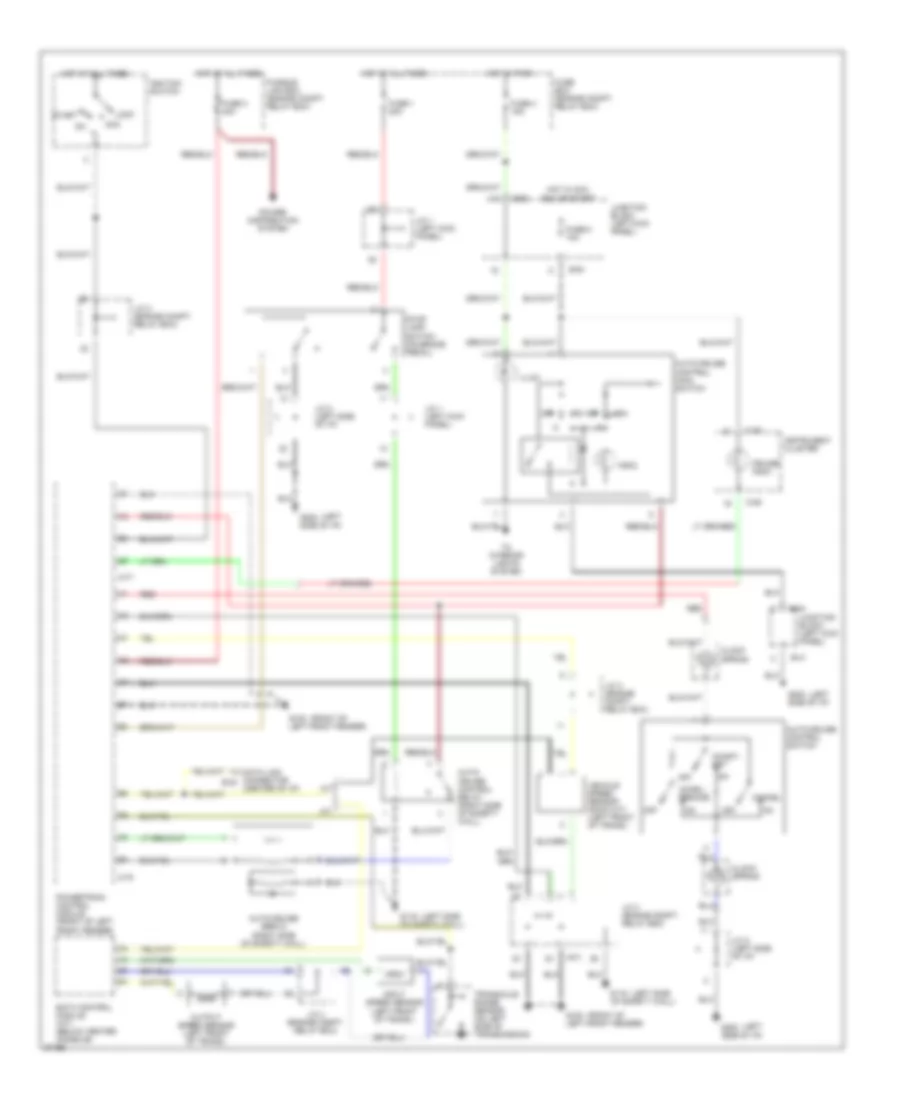
List of elements for Cruise Control Wiring Diagram for Dodge Avenger ES 1997:
- (a/t)
- (center of i/p)
- (front of
- (left
- (left side
- A-77
- A-78
- A/t
- Acc
- Accel/ resume
- Auto- cruise control relay (right side of safety wall)
- Auto-cruise control main switch
- Auto-cruise control switch
- Auto-cruise servo (right side of safety wall)
- B-41
- B-54
- B-63
- C-06
- Cancel
- Clock spring
- Coast/ set
- Cruise indic.
- Data link connector b-30
- Eatx control module (a/t) (below center console)
- Fuse 1 20a
- Fuse 3 40a
- Fuse 4 15a
- Fuse 8 10a
- Fuse box (engine compt. relay box)
- Fusible link box (engine compt. relay box)
- G100 left front fender)
- G116 of safety wall)
- G202 side of i/p)
- Hot at all times
- Hot in acc,
- Hot in park
- Ignition switch
- Illum.
- Indic.
- Input speed sensor (left front of trans.)
- Instrument cluster
- J/c 1 (left kick panel)
- J/c 2 (left side of i/p)
- J/c 3 (engine compt. relay box)
- J/c 4 (engine compt. relay box)
- Junction block (left kick panel)
- Lock
- M/t
- Off
- Output speed sensor (left front of trans.)
- Power distribution system
- Powertrain control module (front of left front fender)
- Red
- Run or start
- Start
- Stop lamp switch (on brake pedal)
- To interior lights system
- Transaxle range sensor (on left side of transmission)
- Vehicle speed sensor (dohc m/t) (left front of trans.)
 Čeština
 Dansk
Dansk Deutsch
 Ελληνικά
 English
 Español
 Suomi
Suomi Français
 Français
 עברית
עברית Hrvatski
 Magyar
 Italiano
 日本語
日本語 한국어
한국어 Nederlands
 Polski
 Português
 Português
 Română
 Русский
 Slovenčina
 Slovenščina
 Svenska
 Türkçe
 中文 (中国)
 English