CRUISE CONTROL
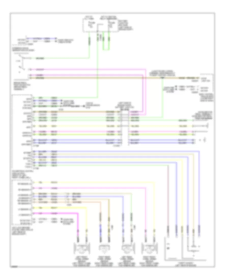
Cruise Control Wiring Diagram for Ford C-Max SEL 2013
List of elements for Cruise Control Wiring Diagram for Ford C-Max SEL 2013:
- (accelerator pedal assembly) accelerator pedal position sensor
- (junction box wiring harness, near breakout to body control module) s120
- (left side of engine compt) battery junction box (bjb)
- (top of transmission) g108
- Anti-lock brakes system (abs) module (left rear of engine compt)
- App1
- App2
- Apprtn1
- Apprtn2
- Appvref
- Appvref2
- Battery junction box (bjb) (left side of engine compt)
- Body control module (bcm) (lower right side of dash)
- Bpp
- Bps
- Brake pedal position switch (brake pedal assembly)
- C1035c
- C175b
- C175e
- C226a
- C2280a
- C2280c
- C238
- C405
- C406
- Cbb42
- Cca29
- Ccb08
- Ce412
- Ce426
- Computer data lines system
- Etcref
- Etcrtn
- Evhs can+
- Evhs can-
- Fuse 5a
- Gd120
- Hot at all times
- Hot w/ ignition relay energized
- Hs can+
- Hs can-
- Isp-r
- Le136
- Le137
- Le428
- Left front wheel speed sensor (left front wheel hub assemblies)
- Left rear wheel speed sensor (left rear wheel hub assemblies)
- Lf sensor hi
- Lf sensor lo
- Lr sensor hi
- Lr sensor lo
- Nca
- Powertrain control module (pcm) (front of left front wheelwell)
- Pwr gnd
- Rca17
- Rca18
- Rca19
- Rca20
- Re136
- Re137
- Re427
- Rf sensor hi
- Rf sensor lo
- Right front wheel speed sensor (right front wheel hub assemblies)
- Right rear wheel speed sensor (right rear wheel hub assemblies)
- Rr sensor hi
- Rr sensor lo
- S126
- Sig rtn
- Steering angle sensor module (sasm)
- Stop light sw
- Tacm+
- Tacm-
- Throttle body (left rear of engine)
- Tp1
- Tp2
- Vca03
- Vca04
- Vca05
- Vca06
- Vdb04
- Vdb05
- Ve701
- Ve702
- Ve818
- Ve819
 Čeština
 Dansk
Dansk Deutsch
 Ελληνικά
 English
 Español
 Suomi
Suomi Français
 Français
 עברית
עברית Hrvatski
 Magyar
 Italiano
 日本語
日本語 한국어
한국어 Nederlands
 Polski
 Português
 Português
 Română
 Русский
 Slovenčina
 Slovenščina
 Svenska
 Türkçe
 中文 (中国)
 English