CRUISE CONTROL
6.4L DIESEL
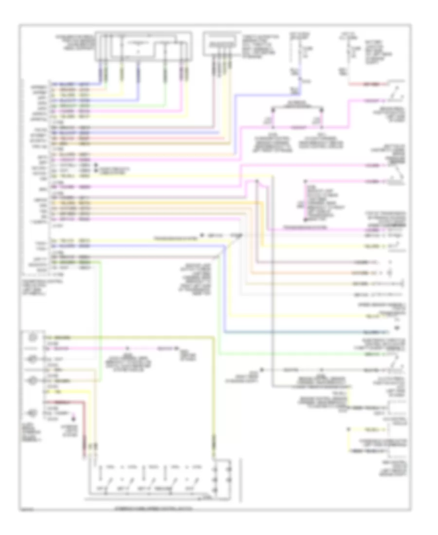
6.4L Diesel, Cruise Control Wiring Diagram for Ford F550 Super Duty 2010
 https://portal-diagnostov.com/license.html
Automotive Electricians Portal FZCO
Automotive Electricians Portal FZCO
https://portal-diagnostov.com/license.html
https://portal-diagnostov.com/license.html
Automotive Electricians Portal FZCO
Automotive Electricians Portal FZCO
List of elements for 6.4L Diesel, Cruise Control Wiring Diagram for Ford F550 Super Duty 2010:
- (backup lamp switch to rear lamp feed harness, near breakout to top of transmission, near left side of transmission)
- (engine control sensor harness, near breakout to left front corner of vehicle) s116
- (engine control sensor harness, near breakout to master cylinder) s130
- (not used)
- 4x4 control module
- Abs control module (left side of engine compt)
- Accelerator pedal position sensor (accelerator pedal support)
- App1
- App2
- Battery junction box (bjb) (left rear of engine compt)
- Bpp
- Bps
- Brake pedal position switch (left side of dash)
- Brake pressure switch (bottom of master cylinder)
- C1232b
- C1232e
- C218a
- C218b
- C281a
- Cbb71
- Ccb08
- Ce904
- Cec11
- Ces09
- Clock spring (steering column assembly)
- Clutch pedal position switch (m/t) (left side of dash)
- Computer data lines system
- Cpp tt
- Engine controls system
- Etcref 2
- Etcref 3
- Etcrtn 2
- Etcrtn 3
- Exterior lights system
- Fuse 10a
- Fuse 5a
- G202 (center of dash)
- Hot at all times
- Hot in run or start
- Hot w/ pcm power relay energized
- Hs can+
- Hs can-
- Interior lights system
- Isp-r
- Iss
- Junction box)
- Le111
- Le136
- Le137
- Off
- Oss
- Output shaft speed (oss) sensor (top of transmission extension housing)
- Powertrain control module (pcm) (left side of firewall)
- Re136
- Re137
- Res08
- Resume
- Ret04
- Ret24
- S1009 (engine control sensor harness, near breakout to right front of engine, on top)
- S101 (engine control sensor harness, near breakout to left front of frame)
- S106 (engine control sensor harness, near breakout to left front of frame)
- S146
- S196
- S198 (backup lamp switch to rear lamp feed harness, near breakout to top of transmission, near tail shaft housing)
- S211 (main harness, near breakout behind audio control module)
- S239 (main harness, near breakout to satellite digital audio receiver system module)
- Sccs
- Sccs rtn
- Set+
- Set-
- Speed sensor assembly (top left of transmission)
- Steering wheel/speed control switch
- Transmission control module (rear of transfer case)
- Transmissions system
- Trgnd
- Tss
- Vbpwr
- Vdb04
- Vdb05
- Ve701
- Ve702
- Ve744
- Ve822
- Ves10
- Vet33
- Vss
- Windshield wiper motor (left side of firewall)
6.8L
6.8L, Cruise Control Wiring Diagram for Ford F550 Super Duty 2010
List of elements for 6.8L, Cruise Control Wiring Diagram for Ford F550 Super Duty 2010:
- (backup lamp switch to rear lamp feed harness, near breakout to front left side of transmission, near top)
- (bottom of master cylinder) brake pressure switch
- (engine control sensor harness, near breakout to master cylinder) s130
- (top of transmission extension housing) output shaft speed (oss) sensor
- 4x4 control module
- Abs control module (left rear of engine compt)
- Accelerator pedal position sensor (accelerator pedal support)
- App1
- App2
- App3
- Appref
- Appref2
- Apprtn
- Apprtn2
- Battery junction box (bjb) (at left rear of engine compt)
- Bpp
- Bps
- Brake pedal position switch (left side of dash)
- C175b
- C175e
- C175t
- C218a
- C218b
- C281a
- Cbb71
- Ccb08
- Ce412
- Ce426
- Ce904
- Ces09
- Clock spring (steering column assembly)
- Clutch pedal position switch (m/t) (left side of dash)
- Computer data lines system
- Cpp tt
- Electronic throttle control (etc) motor (throttle body assembly)
- Etcref1
- Etcrtn1
- Exterior lights system
- Fuse 5a
- G103 (right rear of engine compt)
- G202 (center of dash)
- Hot at all times
- Hot in run or start
- Hs can+
- Hs can-
- Interior lights system
- Isp r
- Iss
- Le111
- Le136
- Le137
- Le428
- Off
- Oss
- Powertrain control module (pcm) (left side of firewall)
- Re136
- Re137
- Re406
- Re427
- Res08
- Resume
- Ret04
- S106 (in engine control sensor harness, near breakout to left front of frame)
- S123
- S162 (engine control sensor harness, near breakout to right rear of engine compt)
- S183
- S196 (backup lamp switch to rear lamp feed harness, near breakout to front left side of transmission, near top)
- S211 (in main harness, near breakout behind audio control module)
- S239 (main harness, near breakout to satellite digital audio receiver system module)
- Sccs
- Sccs rtn
- Set+
- Set-
- Solid state
- Speed sensor assembly (top of transmission)
- Steering wheel/speed control switch
- T sigrtn
- Tacm+
- Tacm-
- Throttle position sensor (tps) (5.4l: throttle body assembly) (6.8l: top center of engine)
- Tp2 ps
- Tps1 ns
- Transmissions system
- Tss
- Vbpwr
- Vdb04
- Vdb05
- Ve701
- Ve702
- Ve703
- Ve744
- Ve818
- Ve819
- Ve822
- Ves10
- Vet33
- Vss
- Windshield wiper motor (left side of firewall)

 Čeština
 Dansk
Dansk Deutsch
 Ελληνικά
 English
 Español
 Suomi
Suomi Français
 Français
 עברית
עברית Hrvatski
 Magyar
 Italiano
 日本語
日本語 한국어
한국어 Nederlands
 Polski
 Português
 Português
 Română
 Русский
 Slovenčina
 Slovenščina
 Svenska
 Türkçe
 中文 (中国)