CRUISE CONTROL
Cruise Control Wiring Diagram (1 of 2) for Hyundai Veloster 2012
 https://portal-diagnostov.com/license.html
Automotive Electricians Portal FZCO
Automotive Electricians Portal FZCO
https://portal-diagnostov.com/license.html
https://portal-diagnostov.com/license.html
Automotive Electricians Portal FZCO
Automotive Electricians Portal FZCO
List of elements for Cruise Control Wiring Diagram (1 of 2) for Hyundai Veloster 2012:
- (center of dash)
- A/c control module
- A/v & navigation head unit
- Accel pedal position sensor (on accelerator pedal assembly)
- Aps 1 gnd
- Aps 1 sig
- Aps 2 gnd
- Aps 2 sig
- Brake lt sw
- Brake test sw
- Cluster fuse 10a
- Data link connector (at lower left side of dash)
- Ecm (left rear of engine compt)
- Ecu 1 fuse 10a
- Eggm-a
- Eggm-k
- Em11
- Etc motor & throttle position sensor (left front of engine on throttle body)
- Etc output (+)
- Etc output (-)
- Exterior
- Hot at all times
- Hot in on or start
- I/p-g
- I/p-h
- I/p-m
- I/p-n
- Leak current autocut device
- Lights system
- M02-b
- M21-b
- Memory fuse 10a
- Motor
- Mr11
- On start input
- Panorama sunroof motor
- Pnk
- Red
- Smart junction box (behind left side of dash)
- Stop lamp fuse 15a
- Stop lamp switch
- Stop signal relay (left side of dash)
- Throttle position sensor
- Tps 1 sig
- Tps 2 sig
- Tps gnd
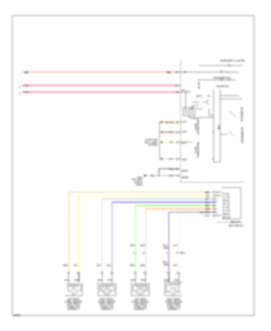
Cruise Control Wiring Diagram (2 of 2) for Hyundai Veloster 2012
List of elements for Cruise Control Wiring Diagram (2 of 2) for Hyundai Veloster 2012:
- C-can transceiver
- Computer data lines
- Cruise ind
- Cruise set ind
- Ef11
- Esc module
- Esc unit
- Fl sig
- Fl vcc
- Fr sig
- Fr vcc
- Gm01 (top left side of dash)
- High
- Instrument cluster
- Left front wheel sensor (left front wheel hub assembly)
- Left rear wheel sensor (left rear wheel hub assembly)
- Low
- Mcu
- Nca
- Output
- Pnk
- Red
- Right front wheel sensor (right front wheel hub assembly)
- Right rear wheel sensor (right rear wheel hub assembly)
- Rl sig
- Rl vcc
- Rr sig
- Rr vcc
- Sgnd1
- Sgnd2
- Speedometer
- System
- Tachometer
- Transceiver b-can

 Čeština
 Dansk
Dansk Deutsch
 Ελληνικά
 English
 Español
 Suomi
Suomi Français
 Français
 עברית
עברית Hrvatski
 Magyar
 Italiano
 日本語
日本語 한국어
한국어 Nederlands
 Polski
 Português
 Português
 Română
 Русский
 Slovenčina
 Slovenščina
 Svenska
 Türkçe
 中文 (中国)