CRUISE CONTROL
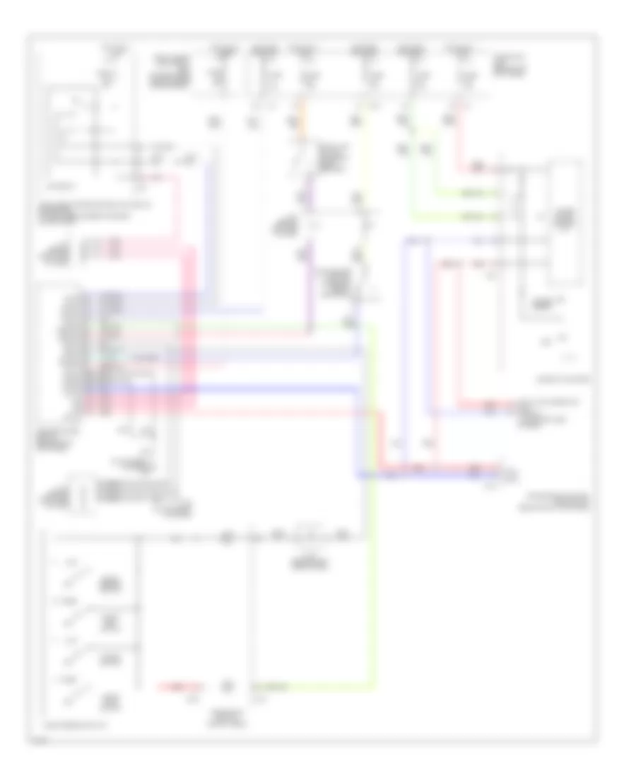
Cruise Control Wiring Diagram for Infiniti G35 2003
List of elements for Cruise Control Wiring Diagram for Infiniti G35 2003:
- (on top front of engine) f23
- 15a
- Accel/ resume switch
- Ascd brake switch (on brake pedal bracket)
- Ascd steering switch
- Ascdsw
- Batt
- Bncsw
- Brksw
- Can-h
- Can-l
- Cancel switch
- Coast/ set switch
- Combination meter
- Combination switch (spiral cable)
- Crtn
- Cruise (green)
- Data link connector (dlc) (partial) (lower left side of dash)
- E101
- Ecm relay
- Engine control module (behind right kick panel)
- F103
- F22 (on top front of engine)
- Fuse 10a
- Fuse 15a
- Fuse block (j/b) (behind left kick panel)
- Fuse, fusible link & relay box (at right rear side of engine compartment)
- Gnd-a
- Gnd-c
- Gnd-e
- Hot at all times
- Hot in on or start
- Ign sw
- Intelligent power distribution module engine room (at right rear corner of engine compartment)
- J/c 2 (behind left side of dash)
- J/c 3 (behind right side of dash)
- J/c 4 (behind right side of dash)
- M20
- M203
- M23
- Off
- On/off (main) switch
- Pnk
- Red
- Set
- Ssoff
- Stop lamp switch (on brake pedal bracket)
- Transmission control module (tcm) (behind right kick panel)
- Unified meter control unit
 Čeština
 Dansk
Dansk Deutsch
 Ελληνικά
 English
 English
 Español
 Suomi
Suomi Français
 Français
 עברית
עברית Hrvatski
 Magyar
 日本語
日本語 한국어
한국어 Nederlands
 Polski
 Português
 Português
 Română
 Русский
 Slovenčina
 Slovenščina
 Svenska
 Türkçe
 中文 (中国)
 Italiano