CRUISE CONTROL
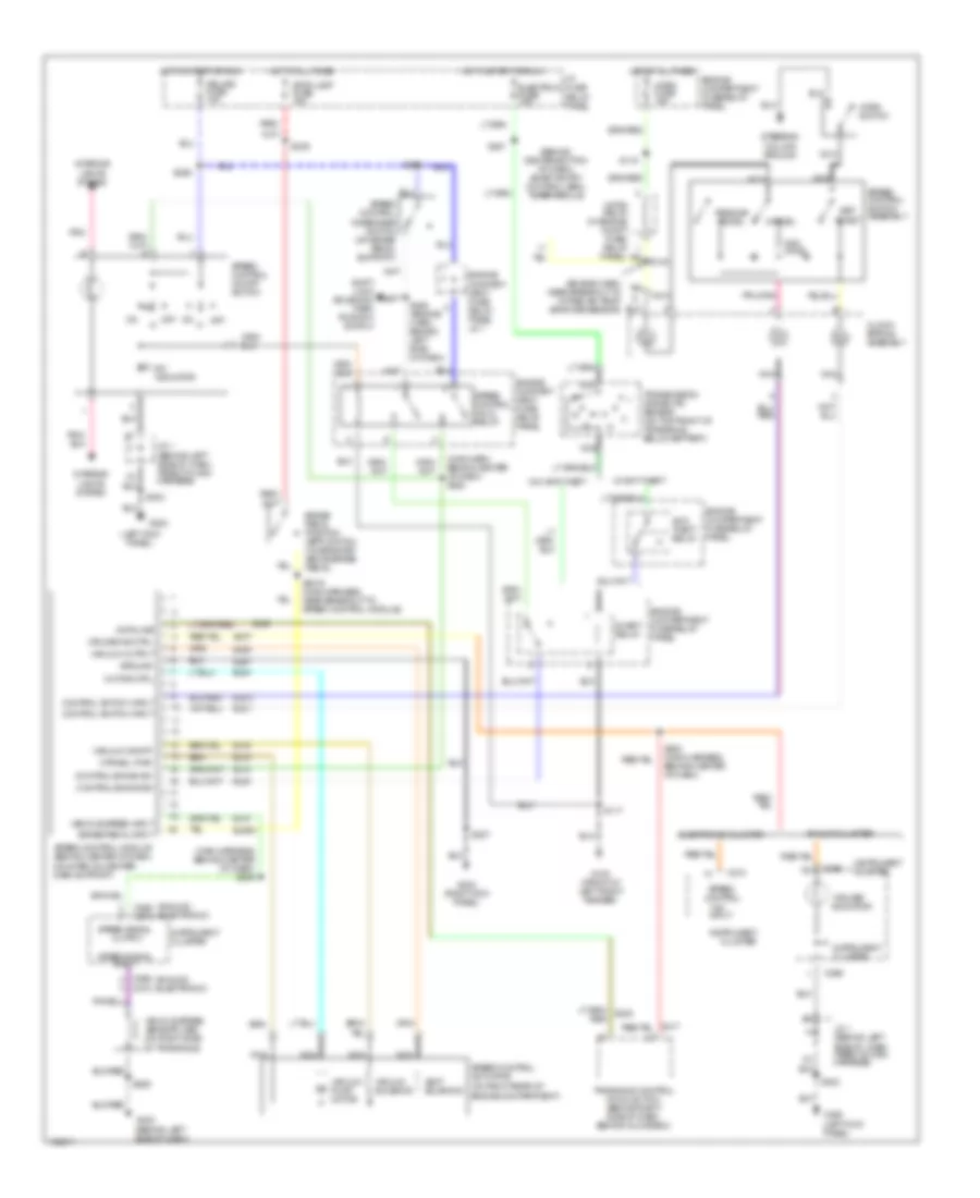
Cruise Control Wiring Diagram for Mercury Villager GS 1998
List of elements for Cruise Control Wiring Diagram for Mercury Villager GS 1998:
- "cruise" indicator
- "on"
- "on" input
- (analog) (electronic)
- (behind center bottom of dash) smart entry control (sec) timer module
- (behind left side of dash, taped to main harness)
- (engine harn, near breakout to intake air temp- erature sensor)
- (left kick panel)
- (main harn, behind center of dash) s282
- (main harness, behind center of dash) s254
- (on right rear of engine compartment)
- Analog cluster
- Anti- theft relay
- Brake pedal input
- Brake pedal position (bpp) switch (on bracket above brake pedal)
- C266
- C268
- C268 c272
- C272
- C274
- Cancel
- Clock- spring assembly
- Cluster
- Control en/dis sw
- Control switch input
- Cruise ind ctrl
- Data line
- Ej04
- Ej06
- Ej07
- Ej08
- Ej09a
- Ej10
- Ej14
- Ej15
- Ej16
- Ej17
- Ej40
- Eje1
- Ejo1
- Ejo2
- Electron fuse 10a
- Electronic cluster
- Engine compart- ment fuse/ relay panel
- Engine compart- ment fuse/ relay panel j/c 1
- Engine compartment fuse/relay panel
- G100 (front of left front fender)
- G200
- G200 (left kick panel)
- G202 (behind left side of dash)
- G203 (right kick panel)
- Ground
- Horn fuse 15a
- Horn relay (in engine compt fuse/ relay
- Horn switch
- Hot at all times
- Hot in start or run
- I/p fuse/ relay panel
- Indicator
- Inhibit relay
- Input
- Instrument
- Instrument cluster
- Interior lights system
- J/c 1
- J/c 1 (behind left side of dash, taped to main harness)
- Motor ctrl
- Mtr/sol pwr
- Nca
- Of transaxle)
- Off
- Ohms
- Output
- Panel)
- Pnk
- Red/
- Relays fuse 10a
- Resume/ accel
- S115
- S117
- S140
- S2016 (main harness, near breakout to speed control module)
- S203
- S207
- S229
- S239
- S247
- S258
- S261
- S283 (main harness, behind center of dash)
- S285 (engine harn, behind left side of dash)
- Set/ coast
- Shift lock solenoid/ park position switch
- Speed control
- Speed control actuator
- Speed control disengage switch (on brake pedal support)
- Speed control hold relay
- Speed control module (behind center of dash, mounted on center dash support)
- Speed control on/off switch
- Speed control switch assembly
- Speed signal
- Steering column ground
- Stop lamp fuse 15a
- Transaxle control module (tcm) (behind right side of dash, behind glove box)
- Transmission range (tr) sensor (on top front of transaxle, below battery)
- Vacuum on/off
- Vacuum output
- Vacuum pump motor
- Vacuum solenoid
- Vehicle speed input
- Vehicle speed sensor (vss) (on right side
- Vent solenoid
- W/ anti-theft
- W/o anti-theft
 Čeština
 Dansk
Dansk Deutsch
 Ελληνικά
 English
 Español
 Suomi
Suomi Français
 Français
 עברית
עברית Hrvatski
 Magyar
 Italiano
 日本語
日本語 한국어
한국어 Nederlands
 Polski
 Português
 Português
 Română
 Русский
 Slovenčina
 Slovenščina
 Svenska
 Türkçe
 中文 (中国)
 English