CRUISE CONTROL
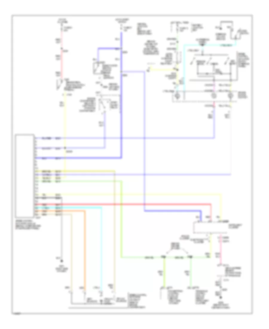
Cruise Control Wiring Diagram for Mercury Villager Sport 2001
List of elements for Cruise Control Wiring Diagram for Mercury Villager Sport 2001:
- (behind center of dash)
- (behind center top of dash) smart entry control (sec) timer module
- (behind left side of dash)
- (in steering wheel) s2021
- (on right rear of engine compartment)
- Air bag sliding contact
- Analog cluster
- Battery junction box
- Brake pedal position switch (above brake pedal)
- C174
- C180
- C247
- C266b
- C267a
- C275
- C277b
- C278
- Cancel
- Central junction box (behind left side of dash)
- Deactivator switch (top of brake pedal support)
- Ej01
- Ej02
- Ej04
- Ej06
- Ej07
- Ej09
- Ej10
- Ej14
- Ej15
- Ej16
- Ej23
- Ej40
- Eje1
- Electronic cluster
- Engine compartment relay box (left front of engine compartment)
- Fuse 13 15a
- Fuse 37 10a
- Fuse 51 20a
- G201 (right side of dash)
- G206 (behind right center of dash)
- Horn relay (in engine compt relay box)
- Horn switch
- Hot at all times
- Hot at all times
- Hot in start or run
- Instrument cluster
- Ohms
- Powertrain control module (behind right side of dash)
- Red
- Red/
- Resume/ accel
- S115
- S140 (in engine compt)
- S2006
- S229
- S239
- S254
- S255
- S258
- S262
- S285
- Set/ coast
- Speed control actuator
- Speed control actuator module (behind lower center of instrument panel)
- Speed control actuator switch (steering wheel)
- Start inhibit relay
- Steering column ground
- Transaxle control module (behind instrument cluster)
- Vacuum pump motor
- Vacuum solenoid
- Vehicle speed sensor (on right side of transaxle)
- Vent solenoid
 Čeština
 Dansk
Dansk Deutsch
 Ελληνικά
 English
 Español
 Suomi
Suomi Français
 Français
 עברית
עברית Hrvatski
 Magyar
 Italiano
 日本語
日本語 한국어
한국어 Nederlands
 Polski
 Português
 Português
 Română
 Русский
 Slovenčina
 Slovenščina
 Svenska
 Türkçe
 中文 (中国)
 English