CRUISE CONTROL
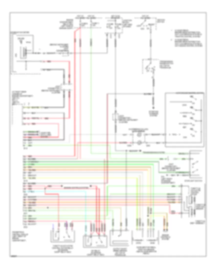
Cruise Control Wiring Diagram for Mitsubishi Endeavor SE 2007
List of elements for Cruise Control Wiring Diagram for Mitsubishi Endeavor SE 2007:
- (at right rear corner of engine compartment) asc/tcl ecu abs/tcl ecu
- (behind instrument cluster) joint connector 3
- (in steering column) clock spring
- (main)
- (sub)
- Acc
- Accelerator pedal position sensor (above accelerator pedal)
- Auto-cruise control switch
- B-18
- B-19
- B-20
- B-21
- B-22
- C211
- C214
- C303
- C306
- Can
- Combination meter
- Computer data lines system
- Cpu
- Cruise ind
- Engine compartment relay box (left side of engine compt)
- Engine controls system
- Fuse 11 15a
- Fuse 7.5a
- Fuse 9 20a
- G12 (left front of engine compartment)
- Hall ic
- Hot at all times
- Hot in on or start
- Ignition switch
- Joint connector 1 (behind instrument cluster)
- Joint connector 4 (behind instrument cluster)
- Junction block (left end of dash)
- Lock
- Main
- Mfi relay (on engine compt relay box)
- Off
- Output shaft speed sensor (on top of transaxle)
- Powertrain control module (left front of engine compartment)
- Red
- Res
- Rheostat circuit
- Set
- Start
- Starting/ charging system
- Stoplight switch
- Throttle actuator control motor
- Throttle actuator control motor relay (on engine compt relay box)
- Throttle body assembly
- Throttle position sensor
- Transmission range switch (on top of transaxle)
- Transmissions system
- W/ electronic brake-force distribution, anti-lock braking system & active skid control system
- W/ electronic brake-force distribution, anti-lock braking system & traction control system
 Čeština
 Dansk
Dansk Deutsch
 Ελληνικά
 English
 Español
 Suomi
Suomi Français
 Français
 עברית
עברית Hrvatski
 Magyar
 Italiano
 日本語
日本語 한국어
한국어 Nederlands
 Polski
 Português
 Português
 Română
 Русский
 Slovenčina
 Slovenščina
 Svenska
 Türkçe
 中文 (中国)
 English