CRUISE CONTROL
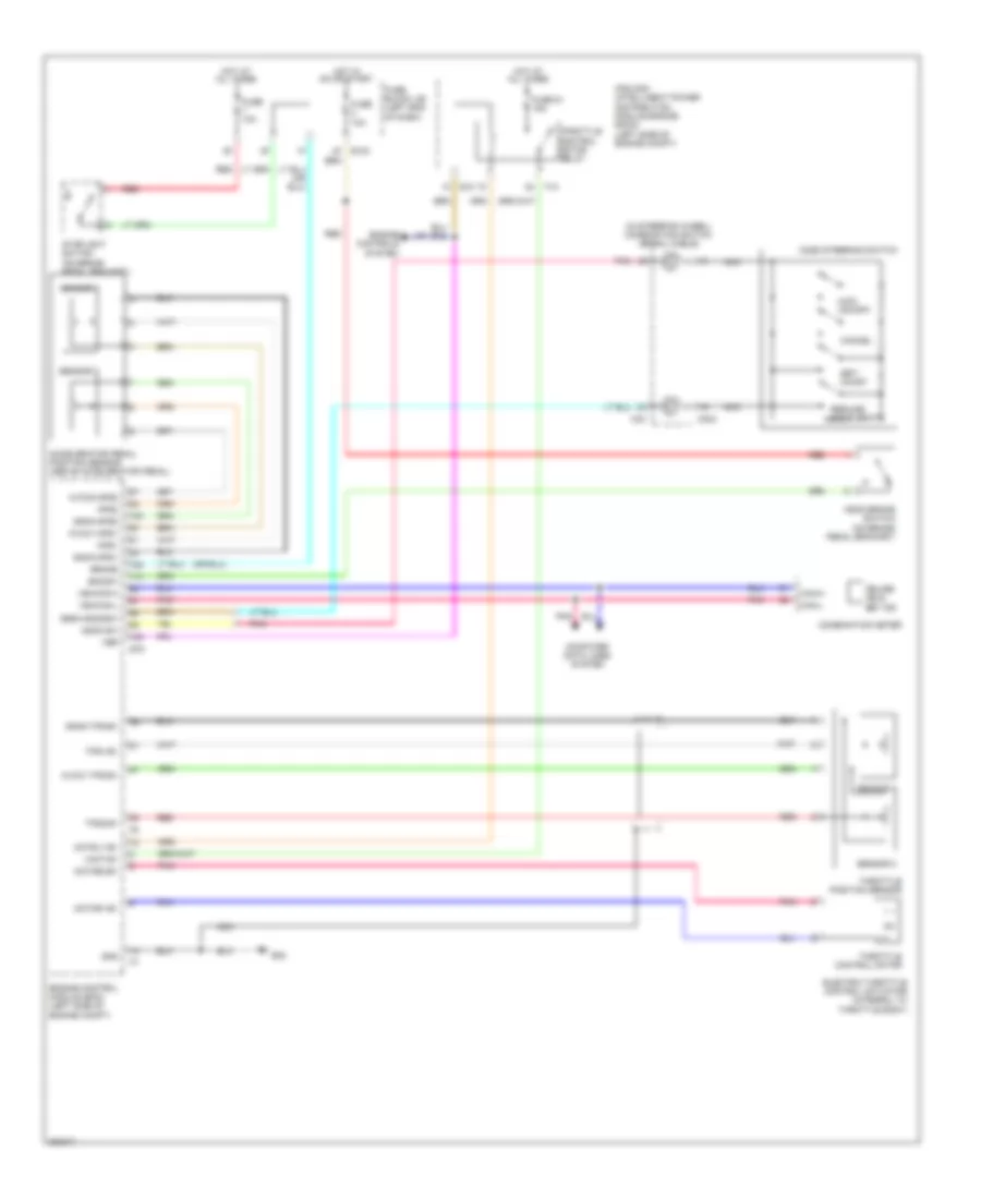
Cruise Control Wiring Diagram for Nissan Murano LE 2010
List of elements for Cruise Control Wiring Diagram for Nissan Murano LE 2010:
- (in steering wheel) combination switch (spiral cable)
- Accelerator pedal position sensor (above accelerator pedal)
- Acsd steering switch
- Aps1
- Aps2
- Ascd brake switch (on brake pedal bracket)
- Ascd sw
- Avcc1-aps1
- Avcc1-tps-b1
- Avcc2-aps2
- Bncsw
- Brake
- Can-h
- Can-l
- Cancel
- Combination meter
- Computer data lines system
- Cruise ind & set ind
- E10
- E103
- E16
- E38
- Electric throttle control actuator (integral to throttle body)
- Engine control module (ecm) (left side of engine compt)
- Engine controls system
- F12
- Fuse 10a
- Fuse 51 15a
- Fuse block j/b (left end of dash)
- Gnd
- Gnda-aps1
- Gnda-aps2
- Gnda-ascdsw
- Gnda-tps-b1
- Hot at all times
- Hot in on or start
- Ipdm e/r (intelligent power distribution module engine room) (left side of engine compt)
- M303
- M33
- Main (on/off)
- Motor1-b1
- Motor2-b1
- Motrly-b1
- Nca
- Pnk
- Red
- Resume/ accelerate
- Sensor 1
- Sensor 2
- Set/ coast
- Stoplight switch (on brake pedal bracket)
- Throttle control motor
- Throttle control motor relay
- Throttle position sensor
- Tps1-b1
- Tps2-b1
- Vbr
- Vehcan-h
- Vehcan-l
- Vmot-b1
 Čeština
 Dansk
Dansk Deutsch
 Ελληνικά
 English
 Español
 Suomi
Suomi Français
 Français
 עברית
עברית Hrvatski
 Magyar
 Italiano
 日本語
日本語 한국어
한국어 Nederlands
 Polski
 Português
 Português
 Română
 Русский
 Slovenčina
 Slovenščina
 Svenska
 Türkçe
 中文 (中国)
 English