CRUISE CONTROL
Cruise Control Wiring Diagram for Pontiac GTO 2006
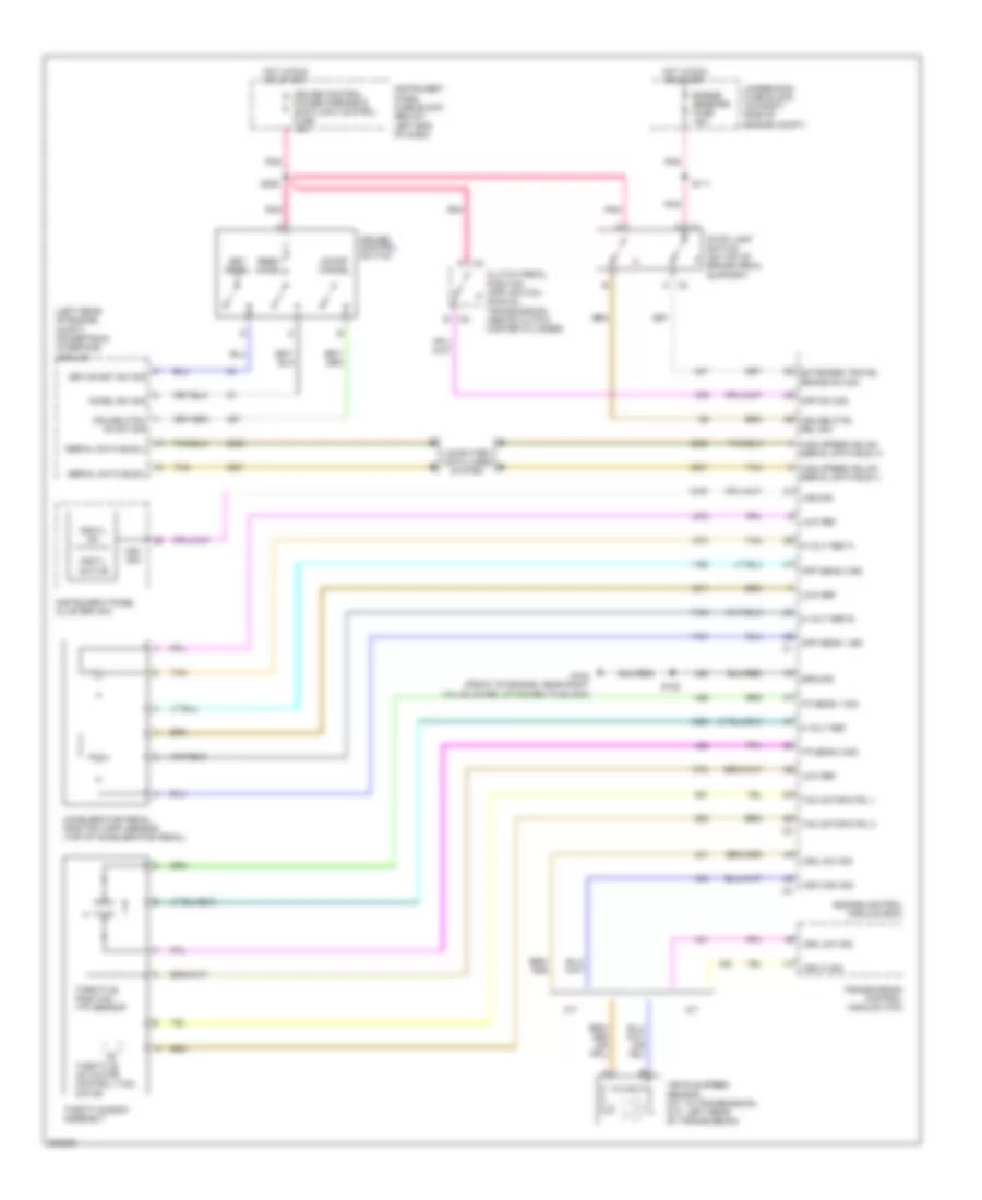
List of elements for Cruise Control Wiring Diagram for Pontiac GTO 2006:
- (left rear of engine compt) powertrain interface module
- 5 volt ref
- 5 volt ref a
- 5 volt ref b
- A/t
- Accel sw sig
- Accelerator pedal position (app) sensor (top of accelerator pedal)
- App sens 1 sig
- App sens 2 sig
- C3 c
- Clutch pedal position (cpp) switch (manual transmission) (above clutch master cylinder)
- Computer data lines system
- Cpp sw sig
- Crctl active
- Crctl on
- Cruise control switch
- Cruise control, power mirrors & shiftlock control fuse 10a
- Cruise ctrl on sw sig
- Cruise ctrl rel sig
- D c3
- Engine control module (ecm)
- Engine sensors fuse 15a
- Extended travel brake sw sig
- G104 (front of engine, near right valve cover, attached to block)
- Ground
- High speed gmlan serial data bus (+)
- High speed gmlan serial data bus (-)
- Hot in run or start
- Instrument panel cluster (ipc)
- Instrument panel fuse block (below left end of dash)
- Low ref
- M/t
- On/off cancel
- Pnk
- Resm accel
- S111
- S128
- S208
- Serial data bus(+)
- Serial data bus(-)
- Set decel
- Set/coast sw sig
- Stop lamp switch (on top of brake pedal support)
- Tac motor ctrl 1
- Tac motor ctrl 2
- Tan
- Throttle actuator control (tac) motor
- Throttle body assembly
- Throttle position (tp) sensor
- Tp sens 1 sig
- Tp sens 2 sig
- Transmission control module (tcm)
- Underhood fuse block (on right side of engine compt)
- Vehicle speed sensor (a/t: in transmission) (m/t: left rear of transmission)
- Vss hi sig
- Vss high sig
- Vss low sig
- Vss sig
 Čeština
 Dansk
Dansk Deutsch
 Ελληνικά
 English
 Español
 Suomi
Suomi Français
 Français
 עברית
עברית Hrvatski
 Magyar
 Italiano
 日本語
日本語 한국어
한국어 Nederlands
 Polski
 Português
 Português
 Română
 Русский
 Slovenčina
 Slovenščina
 Svenska
 Türkçe
 中文 (中国)
 English