CRUISE CONTROL
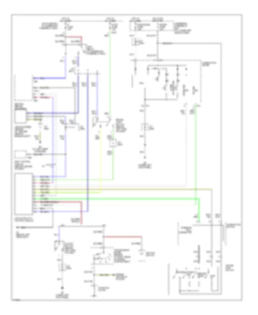
Cruise Control Wiring Diagram for Suzuki XL-7 Limited 2003
List of elements for Cruise Control Wiring Diagram for Suzuki XL-7 Limited 2003:
- A/t
- Actuator with control module
- Body control module (behind center of dash)
- Brake- light switch (behind left side of dash)
- C51-1
- Cancel
- Clutch switch (behind left side of dash)
- Coast/ set
- Combination meter
- Combination switch
- Cpu
- Cruise ind
- Cruise main switch
- E120
- E61
- Ecm/pcm (behind glove box)
- Engine controls system
- Fi fuse 15a
- G10
- G11
- G3 (at left rear of engine)
- G55
- G7 (behind left headlight)
- G9 (under left kick panel)
- Hot at all times
- Hot in on or start
- Ignition switch
- Illum (if equipped)
- J/c (c66)
- J/c (c69)
- J/c (e41)
- J/c (e42)
- J/c (e44)
- J/c (e45)
- J/c (g29)
- M/t
- Main
- Main fuse box (in underhood fuse/relay box)
- Main relay (in underhood fuse/relay box)
- Meter fuse 10a
- Nca
- Radio/dome fuse 15a
- Resume/ accel
- Set ind
- Starting motor
- Steering roll connector
- Stop fuse 15a
- Transmission range sensor (at right rear of engine compartment)
- Underdash fuse/relay box (at lower left side of dash)
- Vehicle speed sensor (at center rear of engine compt)
 Čeština
 Dansk
Dansk Deutsch
 Ελληνικά
 English
 Español
 Suomi
Suomi Français
 Français
 עברית
עברית Hrvatski
 Magyar
 Italiano
 日本語
日本語 한국어
한국어 Nederlands
 Polski
 Português
 Português
 Română
 Русский
 Slovenčina
 Slovenščina
 Svenska
 Türkçe
 中文 (中国)
 English