CRUISE CONTROL
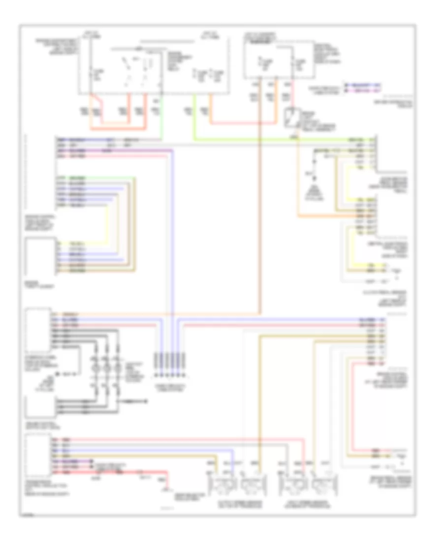
Cruise Control Wiring Diagram for Volvo C70 T-5 2013
List of elements for Cruise Control Wiring Diagram for Volvo C70 T-5 2013:
- 64/111
- 64/90
- A14
- A19
- A45
- A65
- A74
- A75
- A88
- Accelerator pedal sensor (near accelerator pedal)
- B2 nca
- B26
- B27
- B3 nca
- B41
- B5 nca
- B54
- Brake control module (bcm) (at left rear corner of engine compt)
- Brake light contact (at top of brake pedal assembly)
- Brake pedal sensor (at left rear corner of engine compt)
- Central electronic module (cem) (right side of dash)
- Clutch pedal sensor (m/t) (left rear of engine compt)
- Computer data
- Computer data lines system
- Contact reel (top of steering column)
- Cruise control switch unit (sws)
- Driver information module
- E21
- E28
- E41
- Engine compartment distribution box (left side of engine compt)
- Engine control module (ecm) (left front of engine compt)
- Engine management system main relay
- Engine throttle body
- Fuse f18 40a
- Fuse f36 10a
- Fuse f57 15a
- Fuse f68 5a
- Fuse f9 30a
- G12
- G21
- G22
- G23
- G31
- G83 (base of left "a" pillar)
- G84 (base of right "a" pillar)
- Gear selector module (gsm)
- Hot at all times
- Hot w/ comfort functions relay energized
- Input speed sensor (on rear of transaxle)
- Lines system
- Nca
- Output speed sensor (on top of transaxle)
- Red
- Sp1+
- Sp1-
- Sp2+
- Sp2-
- Steering wheel module (swm) (top of steering column)
- Transmission control module (tcm) (a/t) (rear of engine compt)
 Čeština
 Dansk
Dansk Deutsch
 Ελληνικά
 English
 Español
 Suomi
Suomi Français
 Français
 עברית
עברית Hrvatski
 Magyar
 Italiano
 日本語
日本語 한국어
한국어 Nederlands
 Polski
 Português
 Português
 Română
 Русский
 Slovenčina
 Slovenščina
 Svenska
 Türkçe
 中文 (中国)
 English