DEFOGGERS
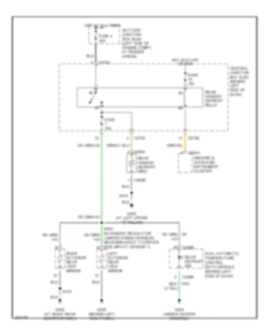
Defoggers Wiring Diagram for Lincoln Aviator 2005
List of elements for Defoggers Wiring Diagram for Lincoln Aviator 2005:
- Battery junction box (bjb) (left side of engine compt, at fender apron)
- C220a
- C228b
- C270a
- C270c
- C270e
- C402a
- C402b
- Central junction box (cjb) (behind left side of dash)
- Dual automatic temperature control (datc) module (behind left side of dash)
- Fuse 10a
- Fuse 15a
- Fuse 4 40a
- G203 (under center console)
- G205 (behind left kick panel)
- G400 (at left upper ``d" pillar)
- G402 (at right rear quarterpanel)
- Hot at all times
- Hot in start or run
- Inboard & outboard instrument cluster
- Jumper wiring harness, near breakout to driver side impact sensor 1)
- Left exterior rear view mirror
- Rear defrost ind
- Rear window defrost grid
- Rear window defrost relay
- Right exterior rear view mirror
- S414
- S415
 Čeština
 Dansk
Dansk Deutsch
 Ελληνικά
 English
 Español
 Suomi
Suomi Français
 Français
 עברית
עברית Hrvatski
 Magyar
 Italiano
 日本語
日本語 한국어
한국어 Nederlands
 Polski
 Português
 Português
 Română
 Русский
 Slovenčina
 Slovenščina
 Svenska
 Türkçe
 中文 (中国)
 English