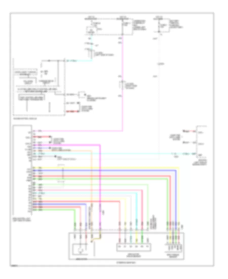
ELECTRONIC POWER STEERING
Electronic Power Steering Wiring Diagram, Electric Vehicle for Honda Fit EV 2014
 https://portal-diagnostov.com/license.html
Automotive Electricians Portal FZCO
Automotive Electricians Portal FZCO
https://portal-diagnostov.com/license.html
https://portal-diagnostov.com/license.html
Automotive Electricians Portal FZCO
Automotive Electricians Portal FZCO
List of elements for Electronic Power Steering Wiring Diagram, Electric Vehicle for Honda Fit EV 2014:
- A10
- A11
- A22
- All times
- B11 b10
- B12
- B13
- B14
- B15
- B16
- Battery terminal fuse box (on battery)
- C401
- Computer data lines system
- Eps control unit (left end of dash)
- Eps ind
- Eps motor (on steering rack)
- Eps motor angle sensor (on eps motor)
- F-can h
- F-can l
- F-can transceiver
- Fail-safe circuit
- Forced turning-
- Fuse 11 7.5a
- Fuse 2 70a
- Fuse 22 7.5a
- G101 (under-dash relay holders 2 & 3)
- G102 (under-dash relay holders 2 & 3)
- G201 (left side of dash)
- Gauge control module
- Hot at
- Hot in on or start
- Indicator drive circuit
- J/c c006 (left center of dash)
- Main circuit
- Management ecu (left side of motor compt)
- Nca
- On circuit
- Pnk
- Red
- Torque sensor (rear of motor)
- Under-dash fuse/relay box (under left end of dash)
Electronic Power Steering Wiring Diagram, Except Electric Vehicle for Honda Fit EV 2014
List of elements for Electronic Power Steering Wiring Diagram, Except Electric Vehicle for Honda Fit EV 2014:
- 5v stabilizer circuit/controller area
- A/t
- A10
- A11
- A29
- A32
- All times
- B10
- B11
- B12
- B13
- B14
- B15
- B16
- B6 b7
- Battery terminal fuse box (on battery)
- C203
- C204
- C309
- Can h
- Can l
- Compulsory turning
- Computer data lines system
- Connector angle sensor eps motor
- Ecm/pcm (left side of engine compt)
- Eps control unit (left end of dash)
- Eps ind
- Eps motor
- Eps motor angle sensor
- Eps motor connector
- Eps torque sensor
- Fail-safe circuit
- Fast controller area network transceiver
- Fuse 11 7.5a
- Fuse 2 70a
- Fuse 22 7.5a
- G203 (left side of dash)
- G501 (behind instrument cluster)
- Gauge control module
- Hot at
- Hot in on or start
- Ig1
- J/c c205 (right side of dash)
- J/c c504 (left side of dash)
- K-line
- Main
- Meter
- Mg1
- Mg2
- Micu
- Nep
- Network controller
- On circuit
- Pnk
- Red
- Steering gear box
- Sub
- Under-dash fuse/relay box (under left end of dash)
- Vcc
- Vref
- Warning drive circuit

 Čeština
 Dansk
Dansk Deutsch
 Ελληνικά
 English
 Español
 Suomi
Suomi Français
 Français
 עברית
עברית Hrvatski
 Magyar
 Italiano
 日本語
日本語 한국어
한국어 Nederlands
 Polski
 Português
 Português
 Română
 Русский
 Slovenčina
 Slovenščina
 Svenska
 Türkçe
 中文 (中国)