ELECTRONIC POWER STEERING
Electronic Power Steering Wiring Diagram for Hyundai XG350 2002
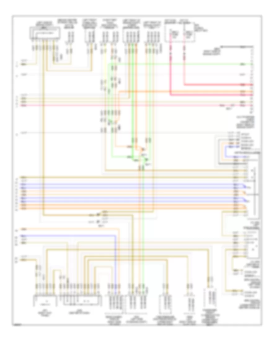
List of elements for Electronic Power Steering Wiring Diagram for Hyundai XG350 2002:
- (behind center of front grille)
- (in battery pack) bms control module
- (left front of engine compt) hybrid control unit
- (left front of engine compt) mcu
- (left front wheelwell) electric oil pump unit
- (left side of engine compt)
- (right side of
- (upper right end of dash)
- 4p out
- Active air flap
- B-can hi
- B-can lo
- B-can low
- C-can hi
- C-can high
- C-can low
- Chg-a
- Chg-k
- Chg34-s
- E/r fuse & relay box
- E64-b
- Ec11
- Ee01
- Em11
- Em61
- Eps control module (left side of dash)
- Esc 2 fuse 30a
- Esc 3 fuse 10a
- Ff01
- Ge04 (right side of engine compt)
- H-can hi
- H-can high
- H-can lo
- H-can low
- Hot at all times
- Hot in on or start
- Hvac unit)
- Instrument cluster
- J/c jm02 (left side of dash)
- J/c jm05 (center of dash)
- Je03
- Jf01 (right kick panel)
- Jm06 (center of dash)
- M-can high
- M-can low
- Mf11
- Mf61
- Monitoring module
- Multipurpose check connector (right rear of engine compt)
- Passenger weight classification sensor (under front passenger's seat)
- Pcm (left side of engine compt)
- Pnk
- Rear camera module (right side of dash)
- Red
- Srs control module (under front of center console)
- Tire pressure
- Vess unit
 Čeština
 Dansk
Dansk Deutsch
 Ελληνικά
 English
 Español
 Suomi
Suomi Français
 Français
 עברית
עברית Hrvatski
 Magyar
 Italiano
 日本語
日本語 한국어
한국어 Nederlands
 Polski
 Português
 Português
 Română
 Русский
 Slovenčina
 Slovenščina
 Svenska
 Türkçe
 中文 (中国)
 English