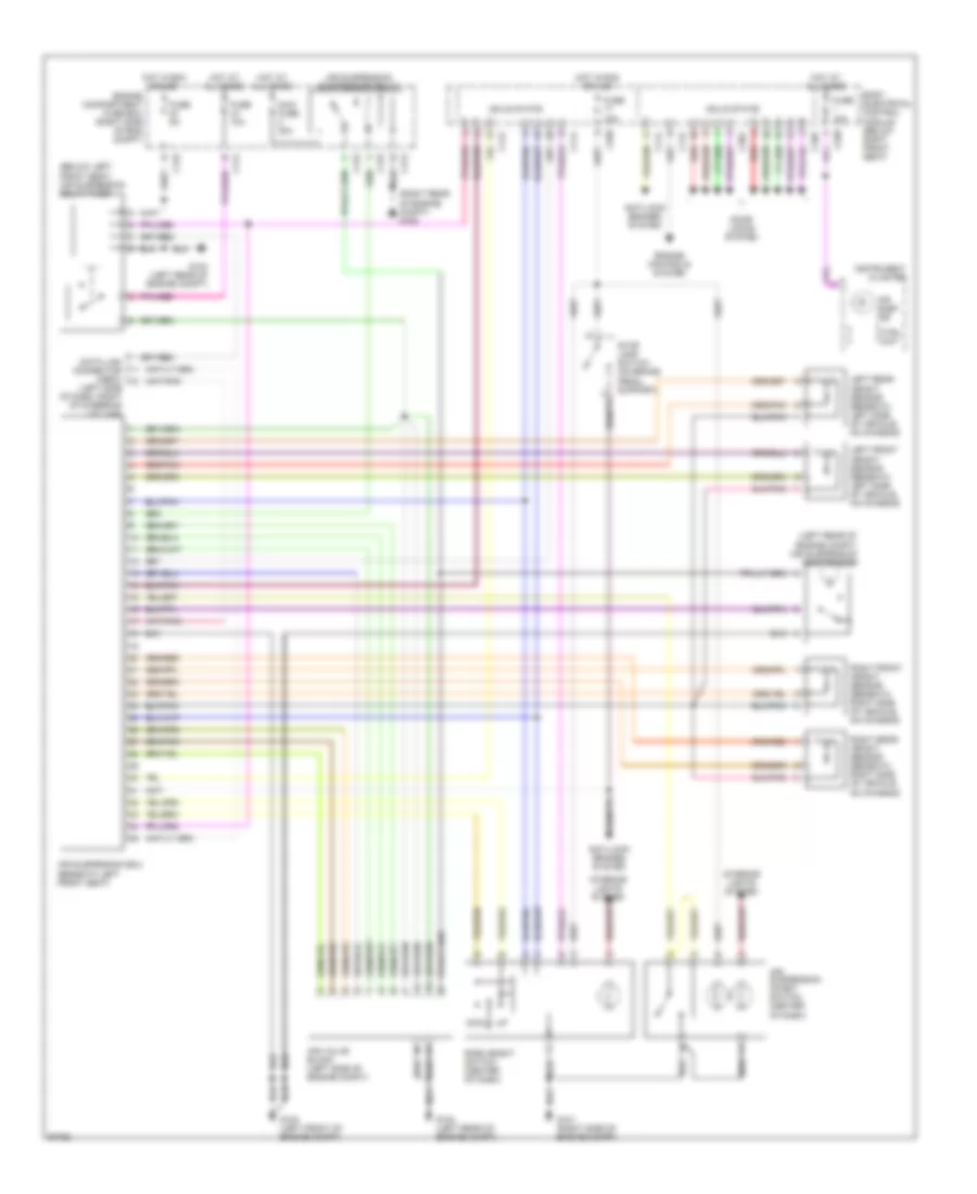
ELECTRONIC SUSPENSION
Electronic Suspension Wiring Diagram for Land Rover Range Rover HSE 1997
List of elements for Electronic Suspension Wiring Diagram for Land Rover Range Rover HSE 1997:
- (below left front seat) air suspension delay timer
- (left rear of engine compt) air suspension compressor
- (left side of dash, right of steering column)
- (right rear of engine compt) g105
- Air susp ind
- Air suspension compressor relay
- Air suspension ecu (beneath left front seat)
- Air suspension inhibit switch (center of dash)
- Air valve block (left side of engine compt)
- Anti-lock brakes system
- Body electrical control module (below right front seat)
- C112
- C114
- C172
- C174
- C176
- C258
- C326
- C362
- Ctrl unit
- Data link connector (obdii)
- Door locks system
- Dwn
- Engine compartment fuse box (right side of eng compt)
- Engine controls system
- Fuse 10a
- Fuse 5a
- G100 (left front of engine compt)
- G101 (right side of engine compt)
- G104 (left rear of engine compt)
- Hot at all times
- Hot in run or acc
- Instrument cluster
- Interior lights system
- Left front height sensor (beneath left side of vehicle, on chassis)
- Left rear height sensor (beneath left side of vehicle, on chassis)
- Maxi fuse 30a
- Red
- Ride height switch (center of dash)
- Right front height sensor (beneath right side of vehicle, on chassis)
- Right rear height sensor (beneath right side of vehicle, on chassis)
- Solid state
- Stop lamp switch (on brake pedal support)
 Čeština
 Dansk
Dansk Deutsch
 Ελληνικά
 English
 Español
 Suomi
Suomi Français
 Français
 עברית
עברית Hrvatski
 Magyar
 Italiano
 日本語
日本語 한국어
한국어 Nederlands
 Polski
 Português
 Português
 Română
 Русский
 Slovenčina
 Slovenščina
 Svenska
 Türkçe
 中文 (中国)
 English