ENGINE PERFORMANCE
3.7L
3.7L, Engine Performance Wiring Diagram (1 of 6) for Acura MDX 2010
 https://portal-diagnostov.com/license.html
Automotive Electricians Portal FZCO
Automotive Electricians Portal FZCO
https://portal-diagnostov.com/license.html
https://portal-diagnostov.com/license.html
Automotive Electricians Portal FZCO
Automotive Electricians Portal FZCO
List of elements for 3.7L, Engine Performance Wiring Diagram (1 of 6) for Acura MDX 2010:
- (behind right kick panel) j/c c208
- (in fuel tank) fuel tank pressure (ftp) sensor
- (left side of engine compt) ect sensor 2
- (right side of engine compt) g101
- (under left side of dash) app sensor
- (under left side of dash) j/c c211
- A/t clutch pressure control solenoid valve b (on transmission housing)
- A/t clutch pressure control solenoid valve c (on transmission housing)
- A10
- A11
- A12
- A13
- A14
- A15
- A16
- A17
- A18
- A19
- A20
- A21
- A22
- A23
- A24
- A25
- A26
- A27
- A28
- A29
- A30
- A31
- A32
- A33
- A34
- A35
- A36
- A37
- A38
- A39
- A40
- A41
- A42
- A43
- A44
- A45
- A46
- A47
- A48
- A49
- Acc
- Air conditioning system
- Anti-theft system
- Apsa
- Apsb
- Atpp
- B10
- B11
- B12
- B13
- B14
- B15
- B16
- B17
- B18
- B19
- B20
- B21
- B22
- B23
- B24
- B25
- Barometer sensor
- Bksw
- Bkswnc
- Canh
- Canl
- Computer data lines system
- Cooling fans system
- Ect2
- Eld
- Engine mount control solenoid (on transmission housing)
- Etcs rly
- Fanh
- Fanl
- Fpc
- Fpcd
- Ftp
- Fuse 10a
- Fuse 15a
- Headlights system
- Hot in on or start
- Iat sensor
- Igp
- Igpls3
- Igpls4
- Igpls5
- Igpls6
- Imofpr
- Imtm
- Inj1
- Inj2
- Inj3
- Inj4
- Inj5
- Inj6
- J/c c105 (middle of engine)
- J/c c212 (right front of engine compt)
- Lg3
- Lsb
- Lsc
- Maf sensor
- Maf/iat sensor (in air intake duct)
- Mcs
- Mrly
- N41
- Pcm (right front of engine compt)
- Pg2
- Pnk
- Pspsw
- Red
- S-net5v
- Scs
- Sdnp
- Sg3
- Sg4
- Sh02s b1
- Shift interlock system
- Sho2s b2
- Sls
- Starting/ charging system
- Strld
- Strly
- Sts
- Sub rly
- Supp
- Tpsa
- Under-dash fuse/relay box (behind left kick panel)
- Vbsol
- Vbsol2
- Vcc3
- Vcc4
- Vcc5
- Vcent b1
- Vcent b2
- Vg+
- Vg-
- Vs b1
- Vs b2
- Vss out
- Vsv
- Vtpsw
- Wen
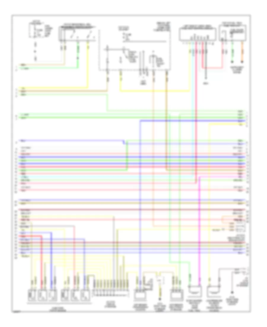
3.7L, Engine Performance Wiring Diagram (2 of 6) for Acura MDX 2010
List of elements for 3.7L, Engine Performance Wiring Diagram (2 of 6) for Acura MDX 2010:
- (behind left kick panel) under-dash fuse/relay box
- (left side of cargo area) fuel pump control module
- (not used)
- (top of brake pedal arm) brake pedal position switch
- (top of fuel tank) fuel tank unit
- Ckp sensor (transmission housing)
- Cmp sensor (right front of engine)
- D10
- E13
- Evap canister vent shut valve (near fuel tank)
- Fp+
- Fp-
- Fpc
- Fpcd
- Fuel gauge sending unit
- Fuel pump short pin
- Fuse 15a
- Fuse 20a
- G101 (right side of engine compt)
- G604
- Gnd
- Hot at all times
- Hot in on or start
- Ig1
- Injectors (top of engine)
- Instrument cluster system
- J/c c103 (middle of engine)
- J/c c104 (middle of engine)
- J/c c105 (middle of engine)
- J/c c212 (right front of engine compt)
- Line pressure solenoid valve a (transmission housing)
- Main under- hood fuse box
- N10
- Pgm-fi main relay 2 (fuel pump)
- Pnk
- Red
- X31
- X38
3.7L, Engine Performance Wiring Diagram (3 of 6) for Acura MDX 2010
List of elements for 3.7L, Engine Performance Wiring Diagram (3 of 6) for Acura MDX 2010:
- (left rear of engine)
- (middle of engine) j/c c103
- (middle of engine) j/c c104
- (rear of engine) rear a/f sensor (b1, s1)
- (right side of engine compt) g101
- (right side of engine compt) power steering pressure (psp) switch
- B16
- Braided wire
- C16
- Cable reel (behind steering column cover)
- Evap canister purge valve (top rear of intake manifold)
- Front a/f sensor (b2, s1)
- Front secondary ho2s (b2, s2)
- G101 (right side of engine compt)
- G202 (right side of engine compt)
- G501 (under left side of dash)
- Interior lights system
- Off
- Paddle shifter
- Paddle shifter+ (upshift switch)
- Paddle shifter- (down shift switch)
- Pnk
- Rear secondary ho2s (b1, s2)
- Red
- Rocker arm oil pressure switch (under right side of engine compt)
- Steering wheel
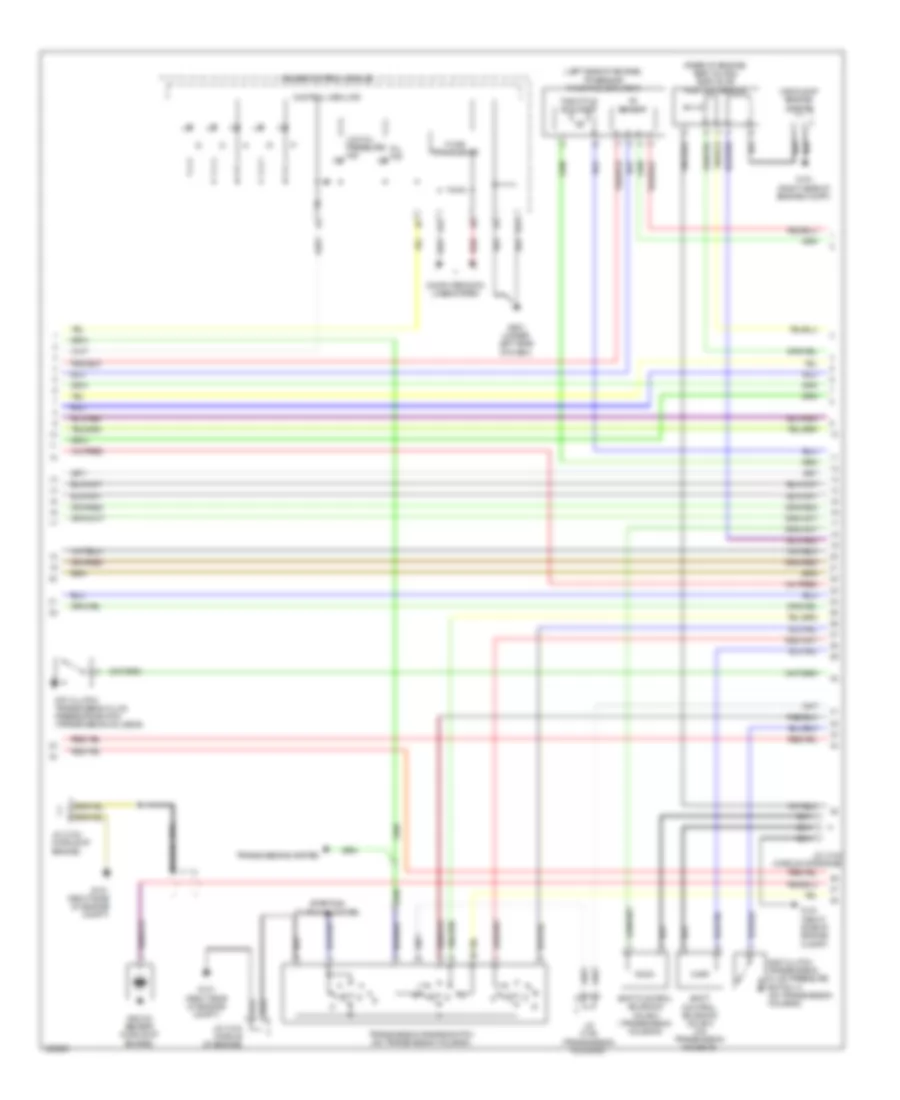
3.7L, Engine Performance Wiring Diagram (4 of 6) for Acura MDX 2010
List of elements for 3.7L, Engine Performance Wiring Diagram (4 of 6) for Acura MDX 2010:
- (top left side of engine)
- (top right side of engine)
- Cooling fans system
- E13
- E14
- Etcs control relay
- Fuse 10a
- Fuse 15a
- Fuse 7.5a
- G101 (right side of engine compt)
- Hot at all times
- Hot in on or start
- Icm
- Ignition coil 1
- Ignition coil 2
- Ignition coil 3
- Ignition coil 4
- Ignition coil 5
- Ignition coil 6
- Ignition coil relay
- J/c c103 (middle of engine)
- J/c c104 (middle of engine)
- J/c c105 (middle of engine)
- J/c c514 (under left side of dash)
- Pgm-fi main relay 1
- Pgm-fi sub-relay
- Red
- Short pin
- Under-dash fuse/relay box (behind left kick panel)
- Under-hood fuse/relay box (right side of engine compt)
- X34
- X35
3.7L, Engine Performance Wiring Diagram (5 of 6) for Acura MDX 2010
List of elements for 3.7L, Engine Performance Wiring Diagram (5 of 6) for Acura MDX 2010:
- (left side of engine) tp sensor/ throttle actuator
- (middle of engine) j/c c104
- (rear of engine) egr valve & egr valve position sensor
- 2nd clutch transmission fluid pressure switch a (on transmission housing)
- 5th clutch transmission fluid pressure switch (transmission housing)
- A12
- B13
- Braided wire
- Computer data lines system
- Control circuits
- F-can transceiver
- G101 (right side of engine compt)
- G501 (under left side of dash)
- Gauge control module
- J/c c104 (middle of engine)
- J/c c106 (transmission housing)
- Knock sensor (middle of engine)
- Low oil pressure ind
- Mil ind
- N r
- Red
- Shift control solenoid valve a (on transmission housing)
- Shift control solenoid valve c (transmission housing)
- Starting/ charging system
- Throttle actuator
- Tp sensor
- Transmission range switch (on transmission housing)
- Transmissions system
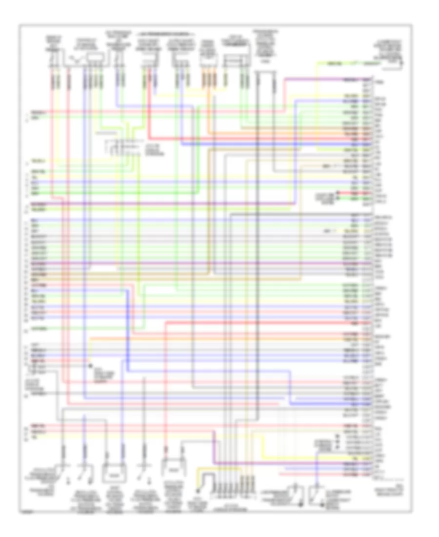
3.7L, Engine Performance Wiring Diagram (6 of 6) for Acura MDX 2010
List of elements for 3.7L, Engine Performance Wiring Diagram (6 of 6) for Acura MDX 2010:
- (on transaxle end cover) atf temperature sensor
- (on transmission housing)
- (rear of engine) ect sensor 1
- (top front of engine) imt actuator
- (top of throttle body) map sensor
- (trans- mission housing) j/c c106
- (transmission housing) a/t clutch pressure control solenoid valve d
- (under right side of engine) rocker arm oil control solenoid valve
- 3rd clutch transmission fluid pressure switch b (on transmission housing)
- 4th clutch transmission fluid pressure switch (on transmission housing)
- 6th clutch transmission fluid pressure switch (transmission housing)
- A/t clutch pressure control solenoid valve a (on trans- mission housing)
- Afshtc b1
- Afshtc b2
- Altc
- Altf
- Altl
- Atft
- Atp-d
- Atp-fwd
- Atp-n
- Atp-r
- Atp-rvs
- Atps
- B26
- B27
- B28
- B29
- B30
- B31
- B32
- B33
- B34
- B35
- B36
- B37
- B38
- B39
- B40
- B41
- B42
- B43
- B44
- B45
- B46
- B47
- B48
- B49
- C10
- C11
- C12
- C13
- C14
- C15
- C16
- C17
- C18
- C19
- C20
- C21
- C22
- C23
- C24
- C25
- C26
- C27
- C28
- C29
- C30
- C31
- C32
- C33
- C34
- C35
- C36
- C37
- C38
- C39
- C40
- C41
- C42
- C43
- C44
- C45
- C46
- C47
- C48
- C49
- Can h2
- Can l2
- Ckp
- Cmp
- Computer data lines system
- Ect1
- Egr
- Egrp
- Etcs m+
- Etcs m-
- G101 (right side of engine compt)
- Iat
- Ig1
- Ig1etcs
- Igpls1
- Igpls2
- Imt (+)
- Imt (-)
- Input shaft (mainshaft) speed sensor
- Ip b1
- Ip b2
- J/c c104 (middle of engine)
- J/c c105 (middle of engine)
- Lg1
- Lg2
- Line pressure switch (transmission housing)
- Lsa
- Lsd
- Map
- Oil pressure switch (under right side of engine)
- Op2sw
- Op3sw
- Op4sw
- Op5sw
- Op6sw
- Opsw
- Output shaft (countershaft) speed sensor
- Pcm (right front of engine compt)
- Pcs
- Pg1
- Pgm etcs
- Pla
- Red
- S02htc b1
- S02htc b2
- Sg1
- Sg2
- Sg5
- Sg6
- Sha
- Shb
- Shc
- Shift control solenoid valve b (on trans- mission housing)
- So2s gb1
- So2s gb2
- Starting/ charging system
- Tpsb
- Vcc1
- Vcc2
- Vcc6
- Vts

 Čeština
 Dansk
Dansk Deutsch
 Ελληνικά
 English
 Español
 Suomi
Suomi Français
 Français
 עברית
עברית Hrvatski
 Magyar
 Italiano
 日本語
日本語 한국어
한국어 Nederlands
 Polski
 Português
 Português
 Română
 Русский
 Slovenčina
 Slovenščina
 Svenska
 Türkçe
 中文 (中国)