ENGINE PERFORMANCE
3.2L
3.2L, Engine Performance Wiring Diagram (1 of 5) for Acura TL 2006
 https://portal-diagnostov.com/license.html
Automotive Electricians Portal FZCO
Automotive Electricians Portal FZCO
https://portal-diagnostov.com/license.html
https://portal-diagnostov.com/license.html
Automotive Electricians Portal FZCO
Automotive Electricians Portal FZCO
List of elements for 3.2L, Engine Performance Wiring Diagram (1 of 5) for Acura TL 2006:
- (a/t)
- (left side of dash) j/c c507
- (m/t)
- (near brake pedal) brake pedal position switch
- (under middle of dash) j/c c512
- Acc
- Afshtcr
- Air conditioning system
- Anti-theft system
- App sensor (right side of engine compt)
- Aps1
- Aps2
- Atp-n
- B10
- B11
- B12
- B13
- B14
- B15
- B16
- B17
- B18
- B19
- B20
- B21
- B22
- B23
- B24
- Bksw
- Bkswnc
- Can h
- Can l
- Ckpa
- Ckpb
- Cmp
- Computer data lines system
- Cooling fans system
- Cruise control system
- Dbwrly
- E10
- E11
- E12
- E13
- E14
- E15
- E16
- E17
- E18
- E19
- E20
- E21
- E22 rvslck sls e23
- E24
- E25
- E26
- E27
- E28
- E29
- E30
- E31
- Ecm/pcm (behind center of dash)
- Egr
- Eld
- Fanh
- Fanl
- Ftp
- Fuse 15a
- Fuse 2 15a
- Fuse 20a
- G101 (left side of engine)
- Hot at all times
- Hot in on or start
- Ig1
- Ignition coil relay
- Imo fpr
- Imocd
- Imt
- Imt +
- Imtm
- Ip b1
- Ip b2
- K-line
- Knock sensor (on top middle of engine, below intake manifold)
- Lg2
- Mcs
- Met-inh
- Moonroof control unit (rear of roof)
- Mrly
- Navigation unit (if equipped) (in trunk, below left side of package tray)
- Pcs
- Pgm-fi main relay 1
- Pgm-fi main relay 2
- Pspsw
- Red
- S-dn
- S-up
- Scs
- Sg3
- Sg4
- Shift inter- lock system
- Sho2s b1
- Sho2s b2
- Throttle actuator control module relay (behind glove box)
- To fuse 23 (diagram 3 0f 5)
- Under- dash fuse/ relay box (behind left end of dash)
- Under-hood fuse/ relay box (left rear of engine compt)
- Vcc3
- Vcc4
- Vcent b1
- Vcent b2
- Vs b1
- Vs b2
- Vssout
- Vsv
- Wen
- X23
- X31
- X32
- X38
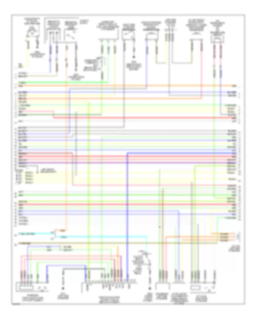
3.2L, Engine Performance Wiring Diagram (2 of 5) for Acura TL 2006
List of elements for 3.2L, Engine Performance Wiring Diagram (2 of 5) for Acura TL 2006:
- (at left side of engine compt, near strut tower) evap canister purge valve
- (behind right side of front bumper)
- (left side of engine compt)
- (left side of engine) j/c c105
- (middle front of trunk) fuel tank unit
- (middle of engine) engine mount control solenoid valve
- (on transmission housing) (a/t) atf temperature sensor
- (right side of engine) psp switch
- (under left rear of vehicle) fuel tank pressure (ftp) sensor
- A/t
- A/t shift switch
- Clutch pedal position switch (m/t) (near clutch pedal)
- Dbw m+
- Dbw m-
- E16
- Fuel pump
- G101 (left side of engine)
- G202
- G503 (under middle of dash)
- G603 (middle front of trunk)
- Imt valve (right side of engine)
- J/c c105
- J/c c105 (left side of engine)
- M/t
- Map sensor (left side of engine)
- Output shaft (countershaft) speed sensor (in transmission housing)
- Pg2
- Red
- Sedf
- Sefd
- Sequential sportshift a/t shift mode switch
- Sequential sportshift mode switch
- Thl1
- Thl2
- Throttle actuator control module (behind glove box)
- Tp sensor/ throttle actuator (on throttle body)
- Under-dash fuse/relay box (behind left x5 end of dash)
- Vcc
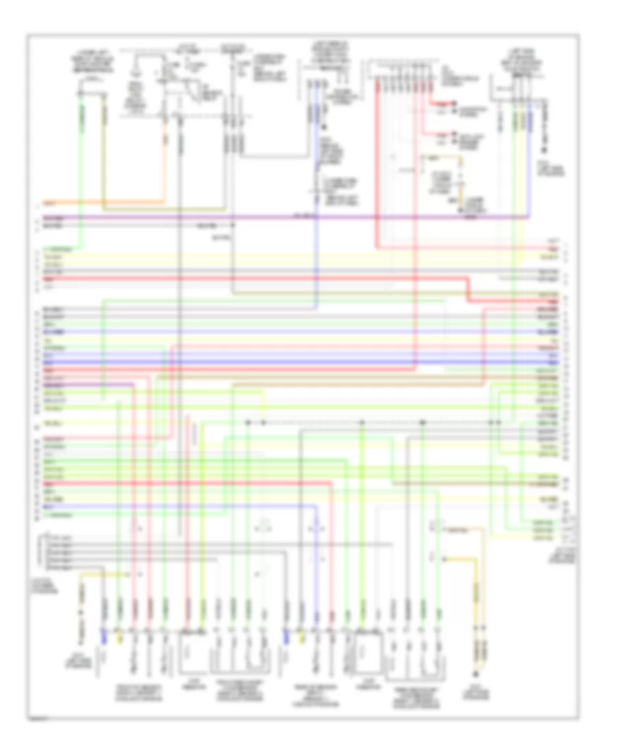
3.2L, Engine Performance Wiring Diagram (3 of 5) for Acura TL 2006
List of elements for 3.2L, Engine Performance Wiring Diagram (3 of 5) for Acura TL 2006:
- (left rear of engine compt) under-hood fuse/relay box
- (left side of engine) egr valve & egr valve position sensor
- (under left rear of vehicle) evap canister vent shut valve
- (under middle of dash) g503
- A/f sensor relay
- Anti-lock brakes system
- Chip resistor
- Eld unit
- From pgm fi main relay 1 (diagram 1 of 5)
- Front a/f sensor (bank 2, sensor 1) (middle of engine)
- Front secondary ho2s sensor (bank 2, sensor 2) (middle of engine)
- Fuse 15a
- Fuse 4 15a
- Fuse 7.5a
- G101 (left side of engine)
- G302 (behind left side of front bumper) d13
- Hot at all times
- Hot in on or start
- J/c c104 (on rear of engine)
- J/c c105 (left side of engine)
- J/c c512 (under middle of dash)
- N29
- Navigation system
- Power distribution system
- Rear a/f sensor (bank 1, sensor 1) (middle of engine)
- Rear secondary ho2s sensor (bank 1, sensor 2) (middle of engine)
- Red
- Under-dash fuse/relay box (behind left end of dash)
- X10
- X36
3.2L, Engine Performance Wiring Diagram (4 of 5) for Acura TL 2006
List of elements for 3.2L, Engine Performance Wiring Diagram (4 of 5) for Acura TL 2006:
- (on outside of transaxle torque converter housing) shift control solenoid valve b
- (on transmission housing) shift control solenoid valve a
- (on transmission housing) shift control solenoid valve c
- (under middle of dash) g503
- A/t clutch pressure control solenoid valves (on transmission housing)
- A/t gear ind/cruise control dimming circuit
- A/t gear position detection circuit
- A/t gear position ind drive circuit
- A/t gear position indicator brightness control & dimming circuit
- A11
- A13
- A14
- B10
- B18
- Drive circuit
- Fast controller area network transceiver
- Fuse 7.5a
- G101 (left side of engine)
- G102 (on right front of engine)
- G151 (on rear of transmission)
- G501
- Gauge control module
- Hot in on or start
- Icm
- Ignition coils (middle of engine)
- Input shaft (mainshaft) speed sensor (in transmission housing)
- J/c c104 (on rear of engine)
- J/c c506 (left side of dash)
- J/c c510 (under middle of dash)
- J/c c512 (under middle of dash)
- Lcd back light
- Micu
- Mil ind
- P16
- P20
- Red
- Torque converter clutch solenoid valve (on transmission housing)
- Under- dash fuse/ relay box (behind left end of dash)
- Warning drive circuit
- X20
- X34
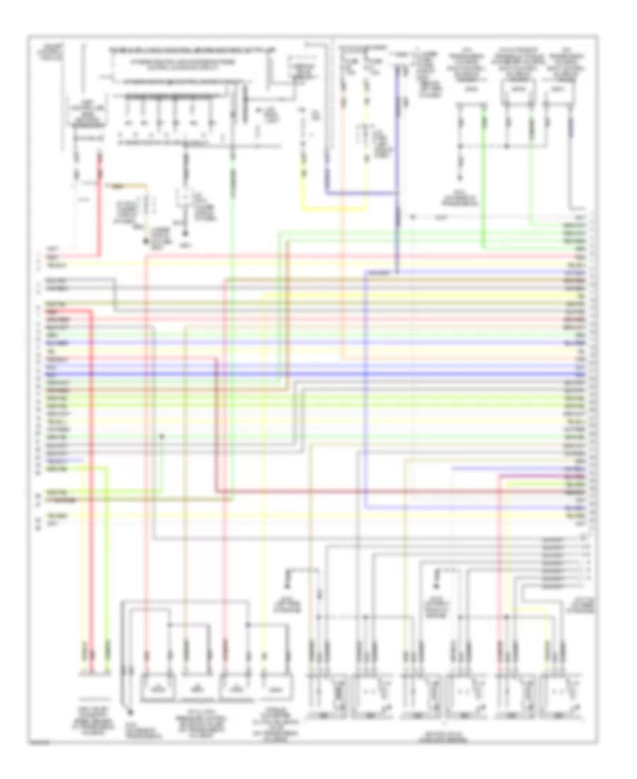
3.2L, Engine Performance Wiring Diagram (5 of 5) for Acura TL 2006
List of elements for 3.2L, Engine Performance Wiring Diagram (5 of 5) for Acura TL 2006:
- (left side of engine) g101
- (middle of engine) fuel injectors
- (not used)
- (on rear of engine) j/c c104
- (right side of engine)
- (right side of engine) cmp sensor
- 3rd clutch transmission fluid pressure switch (on transmission)
- 4th clutch transmission fluid pressure switch (on transmission)
- A10
- A11
- A12
- A13
- A14
- A15
- A16
- A17
- A18
- A19
- A20
- A21
- A22
- A23
- A24
- A25
- A26
- A27
- A28
- A29
- A30
- A31
- Afshtc b1
- Afshtc b2
- Air conditioning system
- Altc
- Altf
- Altl
- Atft
- Atp-d
- Atp-l
- Atp-l2
- Atp-p
- Atp-r
- Barometer sensor
- C10
- C11
- C12
- C13
- C14
- C15
- C16
- C17
- C18
- C19
- C20
- C21
- C22
- Ckp sensors
- D10
- D11
- D12
- D13
- D14
- D15
- D16
- D17
- Ecm/pcm (behind center of dash)
- Ect
- Ect sensor (left side of engine)
- Egrp
- G101 (left side of engine)
- Iat
- Iat sensor (left side of engine)
- Igp
- Igpls1
- Igpls2
- Igpls3
- Igpls4
- Igpls5
- Igpls6
- Inj1
- Inj2
- Inj3
- Inj4
- Inj5
- Inj6
- Lg1
- Lsa
- Lsb
- Lsc
- Map
- Op3sw
- Op4sw
- P-pin
- Pdsw
- Pg1
- Pg2
- Pnk
- Red
- Sedf
- Sefd
- Sg1
- Sg2
- Sha
- Shb
- Shc
- Shift interlock system
- So2shtc b1
- So2shtc b2
- Starting/ charging system
- Transmission range switch (on transaxle)
- Transmission system
- Vbsol
- Vbsol2
- Vcc1
- Vcc2
- Vlbl b1
- Vlbl b2
- Vtec oil pressure switch (right side of engine)
- Vtec solenoid valve
- Vtpsw
- Vts

 Čeština
 Dansk
Dansk Deutsch
 Ελληνικά
 English
 Español
 Suomi
Suomi Français
 Français
 עברית
עברית Hrvatski
 Magyar
 Italiano
 日本語
日本語 한국어
한국어 Nederlands
 Polski
 Português
 Português
 Română
 Русский
 Slovenčina
 Slovenščina
 Svenska
 Türkçe
 中文 (中国)