ENGINE PERFORMANCE
4.6L
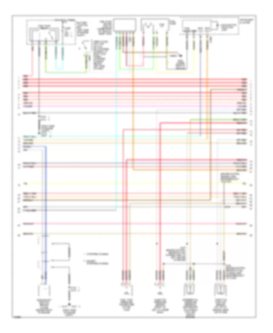
4.6L, Engine Performance Wiring Diagram (1 of 4) for Ford Econoline E350 Super Duty 2004
 https://portal-diagnostov.com/license.html
Automotive Electricians Portal FZCO
Automotive Electricians Portal FZCO
https://portal-diagnostov.com/license.html
https://portal-diagnostov.com/license.html
Automotive Electricians Portal FZCO
Automotive Electricians Portal FZCO
List of elements for 4.6L, Engine Performance Wiring Diagram (1 of 4) for Ford Econoline E350 Super Duty 2004:
- (ends in harness)
- (engine control sensor & fuel charge harn, at left side of engine)
- (engine control sensor & fuel charge harn, at right side of engine)
- (engine control sensor harn, near breakout to c237)
- (engine control sensor harn, near breakout to left rear of engine compt)
- (left front of engine, attached to ignition coil) ignition transformer capacitor 2
- (left side of engine compt)
- (right front of engine, attached to ignition coil) ignition transformer capacitor 1
- (right side of engine compt)
- (right side of engine compt) g107
- A/c on sig
- A/c system
- Air ctrl sens
- Battery junction box (left side of engine compt)
- Central junction box (behind left side of dash)
- Coil on plug
- Coil on plug 1
- Coil on plug 3
- Coil on plug 4
- Coil on plug 5
- Coil on plug 6
- Data link (+)
- Data link (-)
- Data link connector (left side of dash)
- Digital transmission range sensor (dtr sensor) (left side of transmission)
- Dtr sensor (tr1)
- Dtr-tr2
- Dtr-tr4
- Evr sol
- Except stripped chassis
- Feps (eprom)
- Fuse 10a
- Fuse 30a
- G100
- G105
- G107
- G116
- Gnd
- Hot at all times
- Hot in run or start
- Knock sensor
- Maf
- Misfire sens (+)
- Misfire sens (-)
- Nca
- O/d off
- Overdrive cancel switch
- Pcm power diode
- Pcm power relay
- Powertrain control module (left rear of engine compt, near brake master cylinder)
- Pwr gnd
- R n
- Red
- Rr ho2s sig (12)
- S1033
- S1065
- S127
- S140
- S142
- S156
- S161
- S182
- S184
- S216
- Shift sol a
- Shift sol b
- Stripped chassis
- Tach sig
- Tcil ind
- Tcil lamp
- Tcs
- Tft
- To dtr sensor (diagram 4 of 4)
- Vpwr
4.6L, Engine Performance Wiring Diagram (2 of 4) for Ford Econoline E350 Super Duty 2004
List of elements for 4.6L, Engine Performance Wiring Diagram (2 of 4) for Ford Econoline E350 Super Duty 2004:
- (engine control sensor harn, near breakout to c1033)
- (right side of engine compt)
- (right side of engine compt) g116 g107
- Battery junction box (left side of engine compt)
- Bus (+)
- Bus (-)
- Crankshaft position sensor (lower right front of engine)
- Differential pressure feedback egr sensor (top left rear of engine)
- Except stripped chassis
- Fuel level
- Fuel pump relay
- Fuel tank pressure transducer (in fuel tank)
- Fuse 30a 20a
- G107
- G116
- Heated positive crankcase ventilation (pcv) element (top of right cylinder bank)
- Hot at all times
- Injection pressure sensor (top left side of engine)
- Instrument cluster
- Intake manifold tuning valve (top front of engine)
- Malfunction indicator lamp
- Nca
- Red
- Red/pnk
- S138
- S140
- S157 (engine control sensor & fuel charge harn, at left center of engine)
- S158 (engine control sensor & fuel charge harn, near breakout to c1045)
- S172
- Stripped chassis
- Throttle position sensor (on top of engine, near air intake)
- Vref
4.6L, Engine Performance Wiring Diagram (3 of 4) for Ford Econoline E350 Super Duty 2004
List of elements for 4.6L, Engine Performance Wiring Diagram (3 of 4) for Ford Econoline E350 Super Duty 2004:
- (center rear of engine)
- (engine control sensor & fuel charge harn, near breakout to left side of engine)
- (engine control sensor harn, near breakout to left rear of engine)
- (transmission control harn, near breakout at rear of engine)
- 4r70e/4r75e transmission
- Egr vacuum regulator solenoid (above left valve cover, on bracket)
- Electronic pressure control solenoid
- Evap canister purge valve
- Except stripped chassis
- Fuel injectors
- Fuel pump
- Fuel pump driver module (under rear of vehicle, near tank)
- G302 (under rear of vehicle)
- Idle air control valve (rear of engine, near air intake)
- Inertia fuel shut-off switch (ex stripped chassis: at right kick panel) (stripped chassis: behind left side of dash)
- Output shaft speed sensor (left side of transmission)
- Red
- Red/pnk
- S100
- S102
- S136
- S151 (engine control sensor & fuel charge harn, near breakout to right side of engine)
- S152
- Shift solenoids
- Stripped chassis
- Tan
- Tan/ red
- Tan/red
- Torque converter clutch solenoid
- Transmission fluid temperature sensor
4.6L, Engine Performance Wiring Diagram (4 of 4) for Ford Econoline E350 Super Duty 2004
List of elements for 4.6L, Engine Performance Wiring Diagram (4 of 4) for Ford Econoline E350 Super Duty 2004:
- (engine control sensor harn, near breakout to left rear of engine compt)
- (left side of engine compt) speed control servo
- (rear of vehicle, near fuel tank) evap canister vent valve
- (right side of engine compt) g116 g107
- (top of left cyl head) cylinder head temperature sensor
- (top right rear side of engine) knock sensor
- 240 ohms
- 5v ref
- Brake on/off
- Brake pedal position switch
- Camshaft position sensor (front of left cylinder head)
- Central junction box (behind left side of dash)
- Coil on plug 2
- Coil on plug 7
- Coil on plug 8
- Cyl head temp
- Cylinder id
- Digital transmission range sensor (dtr sensor) (left side of transmission)
- Dpfe sens
- Dtr-tr3a
- Epc sol
- Evap sol
- Except stripped chassis
- From dtr sensor (diagram 1 of 4)
- Fuel inj 1
- Fuel inj 2
- Fuel inj 3
- Fuel inj 4
- Fuel inj 5
- Fuel inj 6
- Fuel inj 7
- Fuel inj 8
- Fuel pump ctrl
- Fuel tank press
- Fuse 15a
- G116 g107 (right side of engine compt)
- Heated oxygen sensor (ho2s) 11 (right rear of engine)
- Heated oxygen sensor (ho2s) 12 (right side of transmission)
- Heated oxygen sensor (ho2s) 21 (left rear of engine)
- Heated oxygen sensor (ho2s) 22 (left side of transmission)
- Heater ctrl
- Hot at all times
- Iac sol
- Ips sensor
- Knock sensor
- Lf ho2s
- Lf ho2s sig (21)
- Lr ho2s
- Lr ho2s sig (22)
- Maf sens in
- Mass air- flow sensor (top center of engine compt)
- Nca
- Oss (+)
- Over- head console
- Powertrain control module (left rear of engine compt, near brake master cylinder)
- Pwr gnd
- Red
- Red/pnk
- Rf ho2s
- Rf ho2s sig (11)
- Rr ho2s
- S135 (engine control sensor harn, near breakout to left rear of engine compt)
- S140
- S172
- Sig rtn
- Stripped chassis
- Tan
- Tan/red
- Tcc sol
- Tp sens in
- Vapor valve
- Vbatt
- Vpwr
- Vss (+)
- Vss input
5.4L
5.4L, Engine Performance Wiring Diagram (1 of 4) for Ford Econoline E350 Super Duty 2004
List of elements for 5.4L, Engine Performance Wiring Diagram (1 of 4) for Ford Econoline E350 Super Duty 2004:
- (ends in harness)
- (engine control sensor & fuel charge harn, at right side of engine)
- (engine control sensor & fuel charge harn, near breakout to left side of engine)
- (engine control sensor harn, near breakout to c237)
- (engine control sensor harn, near breakout to left rear of engine compt)
- (left front of engine, attached to ignition coil) ignition transformer capacitor 2
- (left side of engine compt)
- (right front of engine, attached to ignition coil) ignition transformer capacitor 1
- (right side of engine compt)
- (right side of engine compt) g107
- A/c on sig
- A/c system
- Battery junction box (left side of engine compt)
- Central junction box (behind left side of dash)
- Coast sol
- Coil on plug
- Coil on plug 1
- Coil on plug 3
- Coil on plug 4
- Coil on plug 5
- Coil on plug 6
- Data link (+)
- Data link (-)
- Data link connector (left side of dash)
- Digital transmission range sensor (dtr sensor) (left side of transmission)
- Dtr sensor (tr1)
- Dtr-tr2
- Dtr-tr4
- Evr sol
- Except stripped chassis
- Feps (eprom)
- Fuse 10a
- Fuse 30a
- G100
- G105
- G107
- G116
- Gnd
- Hot at all times
- Hot in run or start
- Knock sensor
- Maf
- Misfire sens (+)
- Misfire sens (-)
- Nca
- O/d off
- Overdrive cancel switch
- Pcm power diode
- Pcm power relay
- Powertrain control module (left rear of engine compt, near brake master cylinder)
- Pwr gnd
- R n
- Red
- Rr ho2s sig (12)
- S1033
- S1065
- S127
- S140
- S142
- S156
- S161
- S182
- S184
- S216
- Shift sol a
- Shift sol b
- Stripped chassis
- Tach sig
- Tcil ind
- Tcil lamp
- Tcs
- Tft
- To dtr sensor (diagram 4 of 4)
- Vpwr
5.4L, Engine Performance Wiring Diagram (2 of 4) for Ford Econoline E350 Super Duty 2004
List of elements for 5.4L, Engine Performance Wiring Diagram (2 of 4) for Ford Econoline E350 Super Duty 2004:
- (engine control sensor harn, near breakout to c1033)
- (right side of engine compt)
- (right side of engine compt) g116 g107
- Battery junction box (left side of engine compt)
- Bus (+)
- Bus (-)
- Crankshaft position sensor (lower center front of engine)
- Differential pressure feedback egr sensor (california) (top left side of engine)
- Except stripped chassis
- Fuel level
- Fuel pump
- Fuel pump driver module (under rear of vehicle, near tank)
- Fuel pump relay
- Fuel tank pressure transducer (in fuel tank)
- Fuse 30a 20a
- G107
- G116
- G302 (under rear of vehicle)
- Hot at all times
- Inertia fuel shut-off switch (ex stripped chassis: at right kick panel) (stripped chassis: behind left side of dash)
- Injection pressure sensor (front of left cylinder bank)
- Instrument cluster
- Malfunction indicator lamp
- Red
- Red/pnk
- S138
- S140
- S157 (engine control sensor & fuel charge harn, at left center of engine)
- S158 (engine control sensor & fuel charge harn, near breakout to c1045)
- S172
- Stripped chassis
- Throttle position sensor (on top of engine, near air intake)
- Vref
5.4L, Engine Performance Wiring Diagram (3 of 4) for Ford Econoline E350 Super Duty 2004
List of elements for 5.4L, Engine Performance Wiring Diagram (3 of 4) for Ford Econoline E350 Super Duty 2004:
- (engine control sensor & fuel charge harn, near breakout to c1045)
- (engine control sensor & fuel charge harn, near breakout to left side of engine)
- (engine control sensor harn, near breakout to left rear of engine)
- (left side of transmission) turbine shaft speed sensor
- (right rear of engine)
- (transmission control harn, near breakout at 4r70e/4r75e: rear of engine, 4r100: top of transmission)
- (transmission control harn, near breakout at rear of engine)
- 4r100
- 4r70e/ 4r75e
- Coast clutch solenoid
- Egr vacuum regulator solenoid (california) (above left rear of engine, on bracket)
- Electronic pressure control solenoid
- Evap canister purge valve
- Except stripped chassis
- Fuel injectors
- Idle air control valve (rear of engine, near air intake)
- Output shaft speed sensor (left side of transmission) (rear of transmission)
- Red
- Red/pnk
- S100
- S102
- S136
- S155
- S159
- S160 (engine control sensor & fuel charge harn, at right side of engine)
- Shift solenoid
- Shift solenoid a
- Shift solenoid b
- Stripped chassis
- Tan
- Tan/ red
- Tan/red
- Torque converter clutch solenoid
- Transmission
- Transmission fluid temperature sensor
5.4L, Engine Performance Wiring Diagram (4 of 4) for Ford Econoline E350 Super Duty 2004
List of elements for 5.4L, Engine Performance Wiring Diagram (4 of 4) for Ford Econoline E350 Super Duty 2004:
- (engine control sensor harn, near breakout to c110)
- (engine control sensor harn, near breakout to left rear of engine compt)
- (engine harn, in breakout to left side of engine compt)
- (fuel tank harn, near breakout to c925) s324
- (left side of engine compt) speed control servo
- (rear of vehicle, near fuel tank) evap canister vent valve
- (right side of engine compt) g116 g107
- (top of left cyl head) cylinder head temperature sensor
- (top right rear of engine) knock sensor
- (trans harn, in breakout to right side of transmission)
- 240 ohms
- 5v ref
- Brake on/off
- Brake pedal position switch
- Camshaft position sensor (front of left cylinder head)
- Central junction box (behind left side of dash)
- Coil on plug 2
- Coil on plug 7
- Coil on plug 8
- Cyl head temp
- Cylinder id
- Digital transmission range sensor (dtr sensor) (left side of transmission)
- Dpfe sens
- Dtr-tr3a
- Epc sol
- Evap sol
- Except stripped chassis
- From dtr sensor (diagram 1 of 4)
- Fuel inj 1
- Fuel inj 2
- Fuel inj 3
- Fuel inj 4
- Fuel inj 5
- Fuel inj 6
- Fuel inj 7
- Fuel inj 8
- Fuel pump ctrl
- Fuel tank press
- Fuse 15a
- G116 g107 (right side of engine compt)
- Heated oxygen sensor (ho2s) 11 (right rear of engine)
- Heated oxygen sensor (ho2s) 12 (california) (right side of transmission)
- Heated oxygen sensor (ho2s) 21 (left rear of engine)
- Heated oxygen sensor (ho2s) 22 (california) (left side of transmission)
- Heated oxygen sensor (ho2s) 23 (w/ carbon mngmt system) (right rear of vehicle)
- Heater ctrl
- Hot at all times
- Iac sol
- Ips sensor
- Knock sensor
- Lf ho2s
- Lf ho2s sig (21)
- Lr ho2s
- Lr ho2s sig (22)
- Maf sens in
- Mass air- flow sensor (top center of engine compt)
- Nca
- Oss (+)
- Over- head console
- Powertrain control module (left rear of engine compt, near brake master cylinder)
- Pwr gnd
- Red
- Red/pnk
- Rf ho2s
- Rf ho2s sig (11)
- Rr ho2s
- S119
- S123
- S135 (engine control sensor harn, near breakout to left rear of engine compt)
- S140
- S172
- S179
- S186
- Sig rtn
- Stripped chassis
- Tan
- Tan/red
- Tcc sol
- Tp sens in
- Tss sensor
- Vapor valve
- Vbatt
- Vpwr
- Vss (+)
- Vss input

 Čeština
 Dansk
Dansk Deutsch
 Ελληνικά
 English
 Español
 Suomi
Suomi Français
 Français
 עברית
עברית Hrvatski
 Magyar
 Italiano
 日本語
日本語 한국어
한국어 Nederlands
 Polski
 Português
 Português
 Română
 Русский
 Slovenčina
 Slovenščina
 Svenska
 Türkçe
 中文 (中国)