ENGINE PERFORMANCE
6.8L
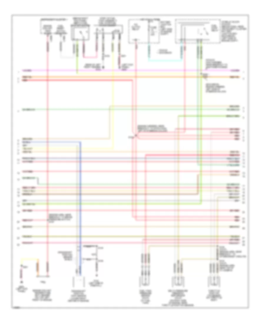
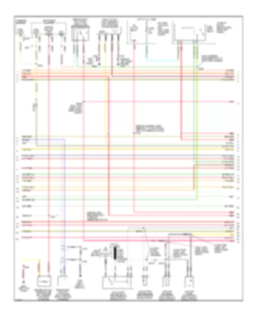
6.8L, Engine Performance Wiring Diagram (1 of 4) for Ford F450 Super Duty 2000
 https://portal-diagnostov.com/license.html
Automotive Electricians Portal FZCO
Automotive Electricians Portal FZCO
https://portal-diagnostov.com/license.html
https://portal-diagnostov.com/license.html
Automotive Electricians Portal FZCO
Automotive Electricians Portal FZCO
List of elements for 6.8L, Engine Performance Wiring Diagram (1 of 4) for Ford F450 Super Duty 2000:
- 31s-pa17
- 31s-pa21
- 31s-pa7
- 8-rj33
- 87a
- 9-re8
- Acc
- Battery junction box (bjb) (in left rear corner of engine compartment)
- C175b
- C270e
- Central junction box (cjb) (behind left side of dash)
- Cooling fan motor diode 1
- Cooling fan motor diode 2
- Cylinder head temperature sensor (on cylinder head)
- Engine cooling fan motor (on radiator)
- Engine cooling fan relay
- Engine cooling fan resistor (in front of engine compartment, near engine cooling fan)
- Fuse 20a
- Fuse 30a
- Fuse 50a
- G102 (at right front
- G104
- High speed fan control relay
- Hot at all times
- Ignition switch
- Lock
- Low speed engine cooling fan relay a
- Low speed engine cooling fan relay b
- Of engine compartment)
- Off
- Pcm power diode
- Power hold relay
- Powertrain control module (pcm) (behind right side of dash, at base of ``a" pillar)
- Red
- Rly ctrl
- Run
- S107
- S109
- S116 (in junction box wiring harness, near battery junction box)
- S117 (in junction box wiring harness, near battery junction box)
- S118
- S134 (in junction box wiring harness, near breakout for c134)
- S137 (in junction box
- S163 (in engine control wiring harness, near breakout for c144)
- S198 (in fuel shut-off solenoid wiring harness, near breakout to coil on plug 3)
- Second cooling fan motor (on radiator)
- Sensor signal
- Signal return
- Start
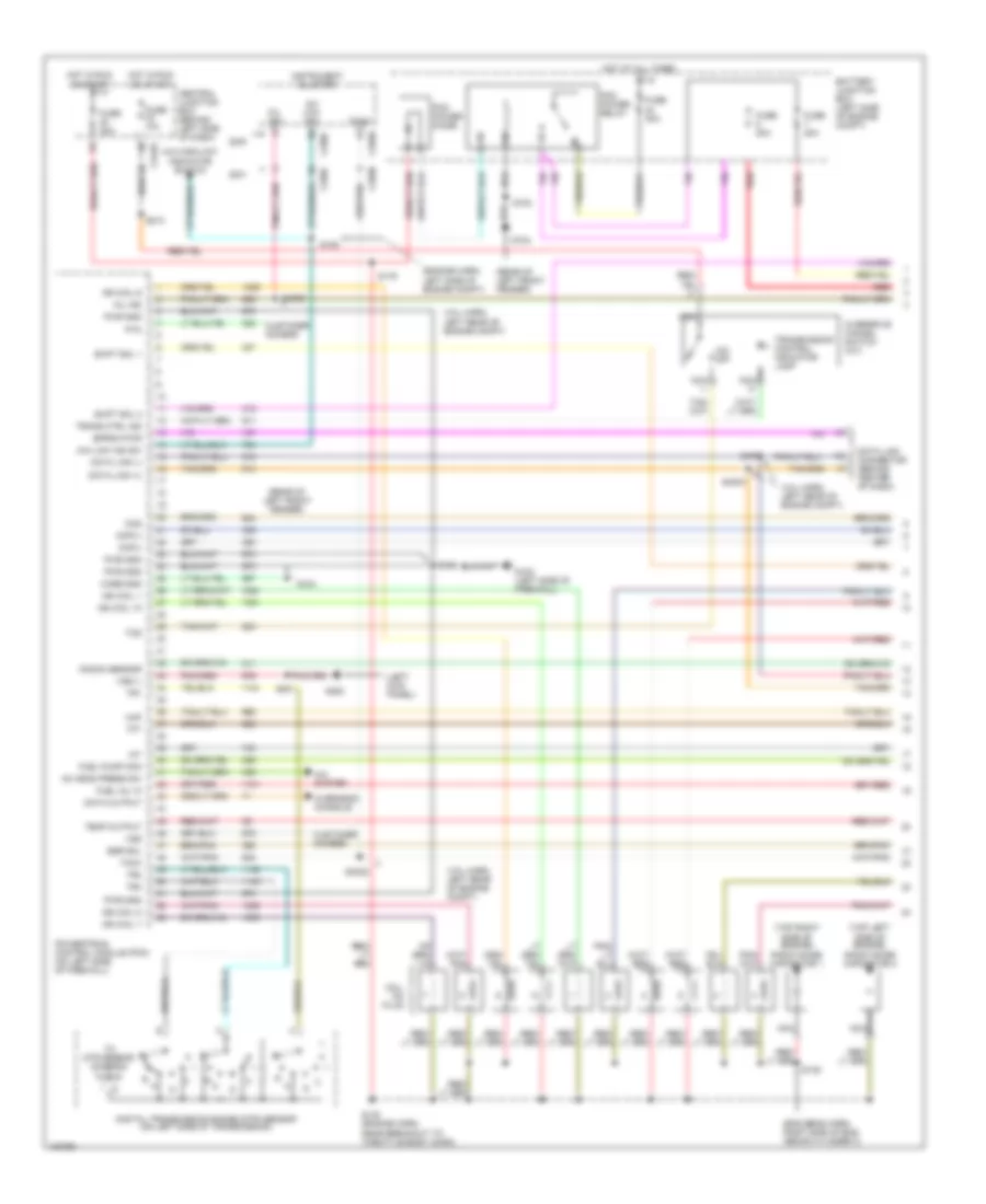
6.8L, Engine Performance Wiring Diagram (2 of 4) for Ford F450 Super Duty 2000
List of elements for 6.8L, Engine Performance Wiring Diagram (2 of 4) for Ford F450 Super Duty 2000:
- (behind right kick panel) inertia fuel shut-off switch
- (engine harn, near breakout to brake pressure switch) s104
- (engine harness, near breakout to 40-pin conn, left of steering column)
- (excursion: engine harness, left side of steering column)
- (left kick panel) g200
- (part of fuel tank assembly) fuel pump/fuel gauge sender
- (pickup: main harness, near breakout to customer access)
- (rear of left front fender) g104
- * **
- A/c clutch relay
- Battery junction box (left side of engine compt)
- C250b
- C250c
- Crankshaft position (ckp) sensor (lower front center of engine)
- Crankshaft position sensor shield
- Delta pressure feedback egr sensor (calif) (on right side of engine, near throttle position sensor)
- Engine coolant temp guage
- Engine coolant temperature (ect) sender (on top left front of engine)
- Fuel pump relay
- Fuel reset switch indicator
- Fuel tank pressure sensor (calif) (at fuel tank)
- Fuse 20a
- G102 (left side of firewall)
- G200 (left kick panel)
- Hot at all times
- I/p relay block (pickup) (behind dash, near instrument cluster) battery junction box (excursion) (left side of engine compt)
- Instrument cluster
- Nca
- Pickup * excursion **
- Red
- Red/pnk
- S102
- S106
- S123
- S128 (calif) (engine harn, near breakout to aftermarket circuits)
- S133 (calif) (engine harn, near top of cylinder 6)
- S145
- S201
- S226 s164
- Throttle position (tp) sensor (on throttle body)
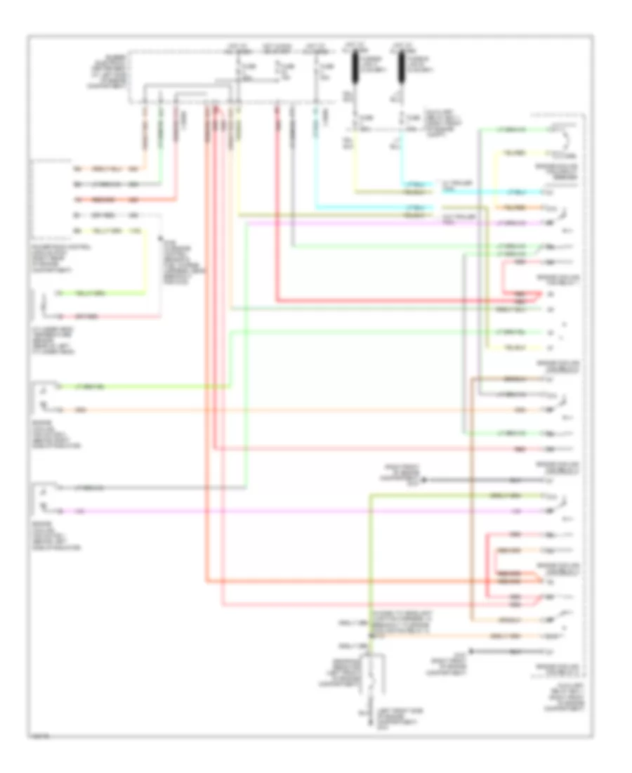
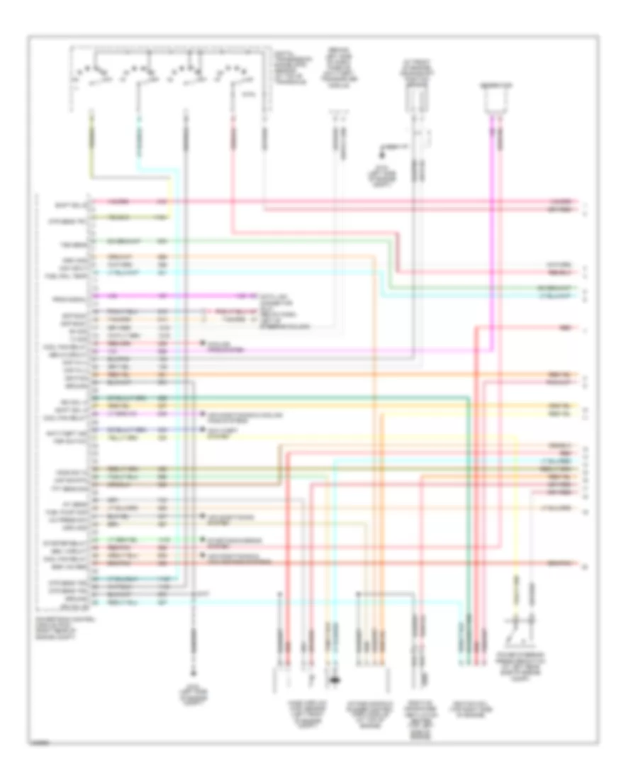
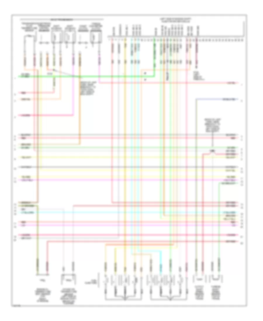
6.8L, Engine Performance Wiring Diagram (3 of 4) for Ford F450 Super Duty 2000
List of elements for 6.8L, Engine Performance Wiring Diagram (3 of 4) for Ford F450 Super Duty 2000:
- (left front side of engine compartment) g101
- (right front of engine compartment) g107
- 10a
- 87a
- A11
- Auxiliary relay box 1 (right front of engine compartment)
- Auxiliary relay box 1 (right front of engine compt)
- Bussed electrical center (bec) (at left side of engine compartment)
- C1035b
- C1035c
- C11
- Cylinder head temperature sensor (rear of left cylinder head)
- Dropping resistor (left front of engine compartment)
- E11
- Engine cooling fan circuit breaker
- Engine cooling fan motor 1 (behind left side of radiator)
- Engine cooling fan motor 2 (behind right side of radiator)
- Engine cooling fan relay 1
- Engine cooling fan relay 2
- Engine cooling fan relay 3
- Engine cooling fan relay 4
- Engine cooling fan relay 5
- F11
- Fuse 15a
- Fuse 30a
- Fuse 40a
- G107 (right front of engine compartment)
- Hot at all times
- Hot in run or start
- Powertrain control module (pcm) (right rear of engine compartment)
- Red
- S106 (in engine control sensor & fuel charge harness, near breakout for g103)
- W/ trailer tow
- W/o trailer tow
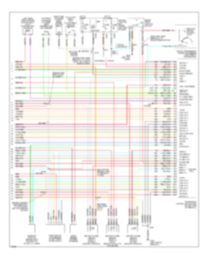
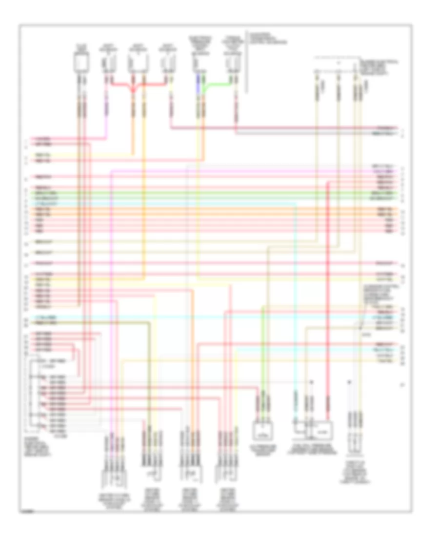
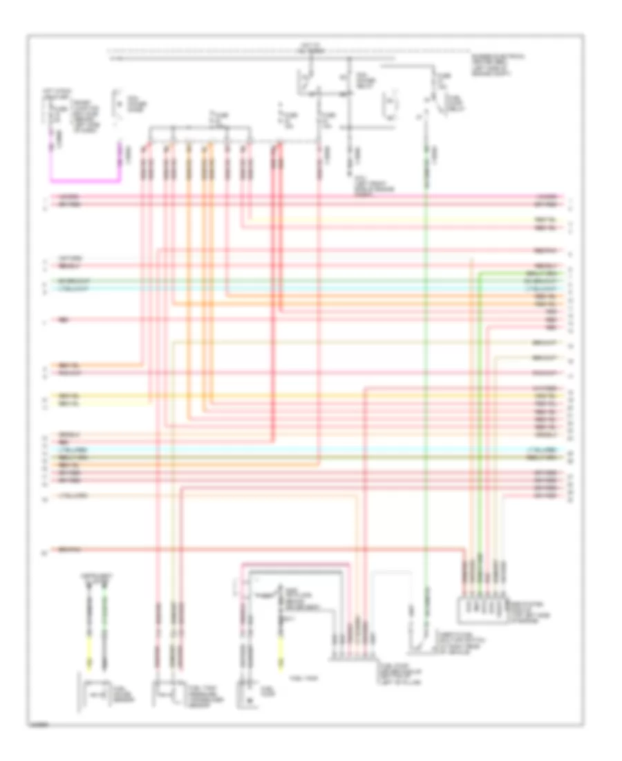
6.8L, Engine Performance Wiring Diagram (4 of 4) for Ford F450 Super Duty 2000
List of elements for 6.8L, Engine Performance Wiring Diagram (4 of 4) for Ford F450 Super Duty 2000:
- (a/t)
- (at clutch pedal) (m/t) clutch pedal position switch
- (calif)
- (eng control sensor harn, at breakout to pcm)
- (eng harn, near breakout to brake press switch)
- (eng sens harn, near top of cyl 8)
- (engine harn, near breakout to 16-pin conn, left side of engine compt)
- (engine harn, near top of cylinder 7)
- (engine harness, near breakout to 40-pin conn, left of steering column)
- (left rear side of engine compartment) (calif) canister vent solenoid
- (m/t)
- (right side of engine compt) speed control servo
- (top front of engine) cylinder head temperature (cht) sensor
- 5v ref volt
- A/c cltch rly
- A/c system
- Anti-lock brakes system
- Bpp sw
- Brake pedal position switch
- C240d
- C242a
- C242b
- Cam pos in
- Camshaft position sensor (cmp) (on front of of left cyl head)
- Canister vent
- Central junction box (under left side of dash)
- Cyl head temp
- Digital transmission range (dtr) sensor (left side of transmission)
- Dpfe sens
- Epc sol
- Evap purge
- Excursion
- From dtr sensor (diagram 1 of 4)
- Fuel inj 1
- Fuel inj 2
- Fuel inj 3
- Fuel inj 4
- Fuel inj 5
- Fuel inj 6
- Fuel inj 8
- Fuel inj 9
- Fuel pump ctrl
- Fuel tank press
- Fuse 15a
- Fuse 5a
- G102 (left side of firewall)
- G200 (left kick panel)
- Gem
- Heated oxygen sensor (ho2s) 11 (on right exhaust manifold)
- Heated oxygen sensor (ho2s) 12 (calif) (rear of catalytic converter)
- Heated oxygen sensor (ho2s) 21 (on left exhaust manifold)
- Heater ctrl
- Hego 11
- Hego 12
- Hego 21
- Hot at all times
- Hot in start
- Iac sol
- Ign coil 2
- Ign coil 3
- Ign coil 4
- Ign coil 7
- Ign coil 8
- Ign coil 9
- Kap b(+)
- Knock sensor
- Knock sensor (on rear of engine)
- Maf sens in
- Mass airflow (maf) sensor (in left front of eng compt)
- Nca
- Oss
- Pickup
- Pickup excursion
- Powertrain control module (pcm) (on left side of firewall)
- Pwr gnd
- Red
- Red/pnk
- S106
- S114
- S115
- S129
- S132
- S134
- S211
- S221 s288
- Sig return
- Tan
- Tan/red
- Tcc sol
- Tp sens in
- Tr3a (a/t) cpp (m/t)
- Tss
- Vpwr
- Vss (+)
- Vss input
6.8L BI-FUEL
6.8L Bi-Fuel, Engine Performance Wiring Diagram (1 of 6) for Ford F450 Super Duty 2000
List of elements for 6.8L Bi-Fuel, Engine Performance Wiring Diagram (1 of 6) for Ford F450 Super Duty 2000:
- (eng sens harn, right side of eng, above cylinder 3)
- (engine harn, left side of engine compt)
- (left kick panel)
- (rear of left front fender)
- (top left side of engine) radio noise capacitor 2
- (top right side of engine) radio noise capacitor 1
- (vcl harn, left rear of engine compt)
- 4x4 high/low indicator switch
- 4x4 low ind sw
- 4x4 low ind
- A/c system
- Ac head press sw
- Battery junction box (left side of engine compt)
- C242b
- C250b
- C250c
- Case gnd
- Ccs
- Central junction box (behind left side of dash)
- Ckp(+)
- Ckp(-)
- Coil on plug
- Customer access
- Data link (+)
- Data link (-)
- Data link connector (behind center of dash)
- Data output
- Digital transmission range (dtr) sensor (on left side of transmission)
- Egr sol
- Eprom pwr
- Fuel inj 10
- Fuel pump mon
- Fuse 10a
- Fuse 20a
- Fuse 30a
- G102 (left side of firewall)
- G104
- G200
- Hot at all times
- Hot in run or start
- Iat
- Ign coil 1
- Ign coil 10
- Ign coil 5
- Ign coil 6
- Ign coil 7
- Instrument cluster
- Knock sensor
- Maf
- Mil ind
- Nca
- O/d off
- Overdrive cancel switch (a/t)
- Overhead console
- Pcm power diode
- Pcm power relay
- Powertrain control module (pcm) (on left side of firewall)
- Pto
- Pwr gnd
- R n
- Red
- S102
- S105
- S106
- S130 (engine harn, near breakout to throttle body conn)
- S135
- S179
- S201
- S213
- S4002
- S4003
- S4004
- S4022
- Shift sol 1
- Shift sol 2
- Tach
- Tcs
- Temp output
- Tft
- To dtr sensor (diagram 6 of 6)
- Tr1
- Tr2
- Tr4
- Trans ctrl ind
- Transmission control indicator lamp
- Vss
- Vss (-)
6.8L Bi-Fuel, Engine Performance Wiring Diagram (2 of 6) for Ford F450 Super Duty 2000
List of elements for 6.8L Bi-Fuel, Engine Performance Wiring Diagram (2 of 6) for Ford F450 Super Duty 2000:
- (behind right kick panel) inertia fuel shut-off switch
- (engine harn, near breakout to brake pressure switch)
- (engine harness, near breakout to 40-pin conn, left of steering column) s123
- (fuel tank harn, right rear of eng compt)
- (in cold start heater harness)
- (in shutoff harn, left rear of eng compt)
- (left kick panel)
- (main harness, near breakout to customer access)
- (part of fuel tank assembly) fuel pump/fuel gauge sender
- (rear of left front fender) g104
- A/c clutch relay
- Battery junction box (left side of engine compt)
- C250b
- C250c
- C911
- Cold start heater
- Cold start heater diode (right rear of engine compt)
- Cold start heater relay (right rear of engine compt)
- Crankshaft position (ckp) sensor (front center of engine)
- Engine coolant temp guage
- Engine coolant temperature (ect) sender (top front of engine)
- Fuel level in
- Fuel pump relay
- Fuse 20a
- Fuse link k 12 ga (near starter motor)
- G102 (left side of firewall)
- G200
- G200 (left kick panel)
- Hot at all times
- I/p relay block (behind dash, near inst panel)
- Instrument cluster
- Lock off diode (cold start) (right rear of engine compt)
- Lock off solenoid (cold start) (right rear of engine compt)
- Nca
- Not used
- Overhead console
- Pnk
- Red
- S102
- S104
- S106
- S145
- S201
- S208
- S226
- S4005 (fuel tank harn, right rear of eng compt)
- S4006
- S4013
- S4014
- S4015
- S4016
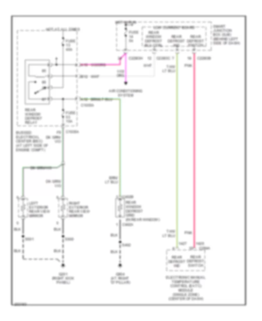
6.8L Bi-Fuel, Engine Performance Wiring Diagram (3 of 6) for Ford F450 Super Duty 2000
List of elements for 6.8L Bi-Fuel, Engine Performance Wiring Diagram (3 of 6) for Ford F450 Super Duty 2000:
- A10
- A12
- Air conditioning system
- B12
- Bussed electrical center (bec) (at left side of engine compt)
- C1035a
- C228ob
- C228oc
- C228oh
- C294a
- C402a
- C402b
- Electronic manual temperature control (eatc) module (single zone) (center of dash)
- Fuse 10a
- Fuse 40a
- Fuse 5a
- G201 (right kick panel)
- G904 (at right "d" pillar)
- Hot at all times
- Hot in run
- Left exterior rear view mirror
- Low current board
- Pnk
- Rear defrost ind
- Rear defrost switch
- Rear window defrost grid (in rear window)
- Rear window defrost relay
- Rear window defrost rly ctrl
- Right exterior rear view mirror
- S402
- S501
- S600
- Smart junction box (sjb) (behind left side of dash)
6.8L Bi-Fuel, Engine Performance Wiring Diagram (4 of 6) for Ford F450 Super Duty 2000
List of elements for 6.8L Bi-Fuel, Engine Performance Wiring Diagram (4 of 6) for Ford F450 Super Duty 2000:
- (b+)
- (compuvalve harness)
- (compuvalve harness) s4023
- (dual tanks)
- (left
- (left rear of engine compt)
- (vcl harn, right rear of engine compt)
- 1ooo
- 87a
- Bi-fuel power relay
- Bi-fuel relay module (left rear of engine compt)
- Bus (+)
- Bus (-)
- Cold st
- Compuvalve module (top rear of engine)
- Cool s
- Coolant solenoid
- D reset
- Digin6
- F cut
- F lvl
- F pump
- F send
- Fuel pump cutoff relay
- Fuse 10a
- Fuse 3a
- G001
- G002
- G003
- G004
- G005
- G006
- G007
- G008
- G009
- G010
- G011
- G013
- G015
- G017
- G019
- G021
- G022
- G027
- G030
- G032
- G042
- G043
- G045
- G046
- G047
- G049
- G050
- G051
- G053
- G055
- G057
- G059
- G061
- G062
- G063
- G064
- G084
- G085
- G086
- G115
- G116
- Ground
- High flow injector assembly
- Ho2s 11
- Ho2s 21
- Hot at all times
- Ign
- Ind sw
- Inj 1
- Inj 2
- Inj 3
- Inj 4
- Inj 5
- Inj 6
- Inj 7
- Inj 8
- Lk off
- Low flow injector assembly
- Mil
- Pnk
- Rear of engine compt)
- Red
- Resistor
- S4001
- S4010
- S4017 (compuvalve harness)
- S4025
- Sig rtn
- Tach
- Tan
- Tps rtn
- Used not
6.8L Bi-Fuel, Engine Performance Wiring Diagram (5 of 6) for Ford F450 Super Duty 2000
List of elements for 6.8L Bi-Fuel, Engine Performance Wiring Diagram (5 of 6) for Ford F450 Super Duty 2000:
- (at front of engine) crankshaft position sensor
- (behind left side of dash) passive anti-theft transceiver module
- A/c press sw
- Air conditioning & cooling fans systems
- Air conditioning system
- Anti-theft ind
- Anti-theft system
- Ckp in (+)
- Ckp in (-)
- Cool fan relay
- Cooling fans system
- Data link connector (dlc) (below dash, left of steering column)
- Digital transmission range (dtr) sensor (at top of transaxle)
- Dtr sens tr1
- Dtr sens tr2
- Dtr sens tr4
- Egr vac reg
- Fuel pump mon
- Fuel rail temp
- G104 (left side of engine compt)
- Gen i circuit
- Gen s circuit
- Generator
- Ground
- Ho2s sig 12
- Iat sens
- Ign coil a
- Ign coil b
- Ignition
- Ignition coil (top right side of engine)
- Imrc mod
- Intake manifold runner control (imrc) module (at top of engine)
- Maf input
- Maf sig rtn
- Mass airflow (maf) sensor (left front of engine compt)
- Nca
- Positive crankcase ventilation heater (top left side of engine)
- Power steering pressure switch (at left rear side of engine compt)
- Powertrain control module (pcm) (right rear of engine compt)
- Prog signal
- Psp switch
- Red
- Red/pnk
- Rx sig
- S107
- Scp bus+
- Scp bus-
- Shift sol a
- Shift sol b
- Starter relay
- Starting/charging system
- Tft sens sig
- Tss sens
- Tx sig
6.8L Bi-Fuel, Engine Performance Wiring Diagram (6 of 6) for Ford F450 Super Duty 2000
List of elements for 6.8L Bi-Fuel, Engine Performance Wiring Diagram (6 of 6) for Ford F450 Super Duty 2000:
- A11
- Bussed electrical center (bec) (left side of engine compt)
- C1035a
- C1035b
- C1035c
- C2280h
- Dpfe
- E10
- Egr system module (top left side of engine)
- Evr+
- Evr-
- Fuel gauge sensor
- Fuel pump
- Fuel pump driver module (bottom of left "b" pillar)
- Fuel pump relay
- Fuel tank
- Fuel tank pressure transducer sensor
- Fuse 10a
- Fuse 15a
- Fuse 5a
- G101 (left front side of engine compt)
- G305 (on floor, behind driver seat)
- Hot at all times
- Hot in run or start
- Inertia fuel shut-off switch (at right rear of vehicle)
- Instrument cluster
- Map
- Nca
- Pcm power diode
- Pcm power relay
- Red
- Red/pnk
- Rtn
- S311
- Smart junction box (sjb) (behind left side of dash)
- Vsupp
7.3L DI TURBO DIESEL
7.3L DI Turbo Diesel, Engine Performance Wiring Diagram (1 of 4) for Ford F450 Super Duty 2000
List of elements for 7.3L DI Turbo Diesel, Engine Performance Wiring Diagram (1 of 4) for Ford F450 Super Duty 2000:
- (in engine control sensor & fuel charge harn, near breakout to g103)
- A/c pressure transducer sensor
- Ax4s/af50n transmission control solenoids
- Bussed electrical center (bec) (left side of engine compt)
- C1035a
- C1035b
- Electronic pressure control (epc) solenoid
- Fluid temp sensor
- Fuel rail pressure temperature sensor (top right side of engine)
- Heated oxygen sensor (ho2s) 11 (in exhaust system)
- Heated oxygen sensor (ho2s) 12 (in exhaust system)
- Heated oxygen sensor (ho2s) 21 (in exhaust system)
- Heated oxygen sensor (ho2s) 22 (in exhaust system)
- Nca
- Pnk
- Red
- Red/pnk
- S102
- Shift solenoid a
- Shift solenoid b
- Shift solenoid c
- Throttle position (tp) sensor (top rear of engine, on throttle body)
- Torque converter clutch (tcc) solenoid
7.3L DI Turbo Diesel, Engine Performance Wiring Diagram (2 of 4) for Ford F450 Super Duty 2000
List of elements for 7.3L DI Turbo Diesel, Engine Performance Wiring Diagram (2 of 4) for Ford F450 Super Duty 2000:
- A/c clutch relay
- A/c press sw
- Air conditioning system
- Battery b+
- Bussed electrical center (bec) (at left side of engine compt)
- C1035b
- Cam pos sig
- Camshaft position sensor (at top right side of engine)
- Cyl head temp
- Cylinder head temperature sensor (rear of left cylinder head)
- Dpfe sens
- Dtr sens tr3a
- Epc sol ctrl
- Evap can purge
- Evap can vent
- Evap canister purge valve (top right of engine)
- Evap canister vent valve (under rear of vehicle)
- Ftpt sens
- Fuel inj 1
- Fuel inj 2
- Fuel inj 3
- Fuel inj 4
- Fuel inj 5
- Fuel inj 6
- Fuel injectors (fuel injectors 1, 2 & 3: top right side of engine) (fuel injectors 4, 5 & 6: top left side of engine)
- Fuel pump ctrl
- Fuel rail press
- Fuse 10a
- G104 (left side of engine compt)
- Ground
- Ho2s 11 htr
- Ho2s 11 sig
- Ho2s 12 htr
- Ho2s 21 htr
- Ho2s 21 sig
- Ho2s 22 htr
- Ho2s 22 sig
- Hot at all times
- Iac valve ctrl
- Idle air control (iac) valve (on throttle body)
- Ign coil c
- Ignition
- Maf sens out
- Oss sig
- Output shaft speed (oss) sensor (on transmission)
- Powertrain control module (pcm) (right rear of engine compt)
- Red
- Red/pnk
- Ref volt
- S105 (in engine control sensor & fuel charge harness, near breakout to rear center of engine compt)
- S106 (in engine control sensor & fuel charge harn, near breakout to g103)
- S107
- S144 (fuel charge harness, near breakout to c139)
- Shift sol c
- Sig rtn
- Tan
- Tcc sol ctrl
- Tps sig
- Turbine shaft speed (tss) sensor (on top of transmission)
7.3L DI Turbo Diesel, Engine Performance Wiring Diagram (3 of 4) for Ford F450 Super Duty 2000
List of elements for 7.3L DI Turbo Diesel, Engine Performance Wiring Diagram (3 of 4) for Ford F450 Super Duty 2000:
- (back-up lamp harn, near breakout to 16-pin conn left side of eng compt)
- (back-up lamp harn, near breakout to 16-pin conn, left side of eng compt)
- (left side of engine compt)
- 4r100 transmission
- Cid sig in
- Coast clutch solenoid
- Electronic pressure control solenoid
- Engine oil temperature (eot) sensor (top front of engine)
- Feedback
- Fuel inj 1
- Fuel inj 2
- Fuel inj 3
- Fuel inj 4
- Fuel inj 5
- Fuel inj 6
- Fuel inj 7
- Fuel inj 8
- Fuel injectors
- Fuel sig
- G102 (left side of firewall)
- Inj feed
- Injector driver module
- Intake air temperature sensor (left side of engine compt, behind air cleaner)
- Nca
- Output shaft speed sensor (top of trans)
- Pwr gnd
- Pwr in
- Red
- S138
- S139
- Shield
- Shift solenoid
- Sig rtn
- Tan
- Tan/red
- Torque converter clutch solenoid
- Transmission fluid temperature sensor
- Turbine shaft speed sensor (top of trans)
7.3L DI Turbo Diesel, Engine Performance Wiring Diagram (4 of 4) for Ford F450 Super Duty 2000
List of elements for 7.3L DI Turbo Diesel, Engine Performance Wiring Diagram (4 of 4) for Ford F450 Super Duty 2000:
- A11
- Bussed electrical center (bec) (left side of engine compt)
- C1035a
- C1035b
- C1035c
- C2280h
- Dpfe
- E10
- Egr system module (top left side of engine)
- Evr+
- Evr-
- Fuel gauge sensor
- Fuel pump
- Fuel pump driver module (bottom of left "b" pillar)
- Fuel pump relay
- Fuel tank
- Fuel tank pressure transducer sensor
- Fuse 10a
- Fuse 15a
- Fuse 5a
- G101 (left front side of engine compt)
- G305 (on floor, behind driver seat)
- Hot at all times
- Hot in run or start
- Inertia fuel shut-off switch (at right rear of vehicle)
- Instrument cluster
- Map
- Nca
- Pcm power diode
- Pcm power relay
- Red
- Red/pnk
- Rtn
- S311
- Smart junction box (sjb) (behind left side of dash)
- Vsupp

 Čeština
 Dansk
Dansk Deutsch
 Ελληνικά
 English
 English
 Español
 Suomi
Suomi Français
 עברית
עברית Hrvatski
 Magyar
 Italiano
 日本語
日本語 한국어
한국어 Nederlands
 Polski
 Português
 Português
 Română
 Русский
 Slovenčina
 Slovenščina
 Svenska
 Türkçe
 中文 (中国)