ENGINE PERFORMANCE
4.6L
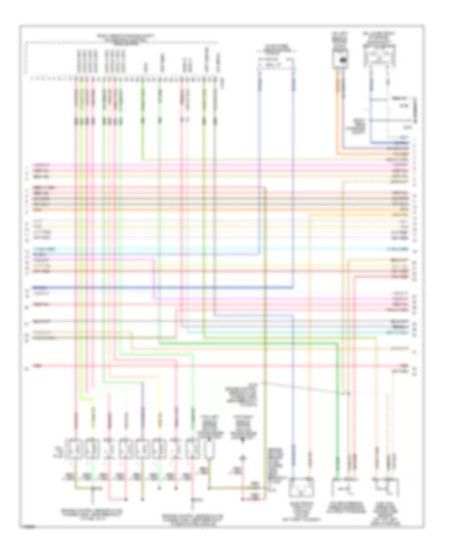
4.6L, Engine Performance Wiring Diagram (1 of 6) for Ford Pickup F150 2004
 https://portal-diagnostov.com/license.html
Automotive Electricians Portal FZCO
Automotive Electricians Portal FZCO
https://portal-diagnostov.com/license.html
https://portal-diagnostov.com/license.html
Automotive Electricians Portal FZCO
Automotive Electricians Portal FZCO
List of elements for 4.6L, Engine Performance Wiring Diagram (1 of 6) for Ford Pickup F150 2004:
- (ccw) 4 x 4 relay
- (cw) 4 x 4 relay
- (engine control sensor harn, near
- (engine control sensor harn, near breakout to g102) s106
- (near center of dash)
- (right kick panel) g206
- (right rear of engine compt) g102
- (right rear of engine compt) g103
- 4 x 4 center axle disconnect solenoid (on right side of engine compt)
- 4 x 4 sol cntl
- 4wd sw
- A/c cltch prs sw
- A/c cltch rly
- A/c system
- Abs control module breakout)
- Airbag dep sig
- Anti-theft on ind
- Anti-theft system
- Apps sig 1
- Apps sig 2
- Apps sig 3
- Audio unit
- Aux spd cntl
- Battery
- Brk ped pos sw
- C125
- C175b
- C270a
- C270b
- C270d
- C270f
- C270g
- C270k
- C290a
- Can bus +
- Can bus -
- Central junction box (near right "a" pillar)
- Computer data lines system
- Cruise control system
- Data link connector
- Deactivator sw
- Etc module
- Evap can vnt vlv
- Evap canister vent control solenoid (vehicle underbody)
- Feps
- Ftpt sens
- Ftpt sens sig
- Fuel pmp drv mod
- Fuel tank pressure transducer sensor (at fuel tank)
- Fuse 15a
- Fuse 20a
- Fuse 30a
- Fuse 5a
- Fuse 7.5a
- Generator com
- Generator mon
- Ground
- Hot at all times
- Hot in run or start
- Iat sens sig
- Maf sens sig
- Mass airflow/ intake air temp- erature sensor (in air cleaner assembly)
- O/d cancel sw
- Pcm power diode
- Pcm power relay
- Pcm pwr relay
- Power
- Powertrain control module (pcm) (right rear of engine compt)
- Red
- Red/pnk
- Rx sig
- S102
- S103
- S104 (engine control sensor harn, near breakout to c139)
- S105
- S107
- S117
- S118
- S140
- S199
- S355
- Sig rtn
- Start relay
- Starting/charging system
- Tan
- To fuel pump relay (diagram 5 of 6)
- Tx sig
- Vss
- Windshield wiper motor (left rear of engine compt)
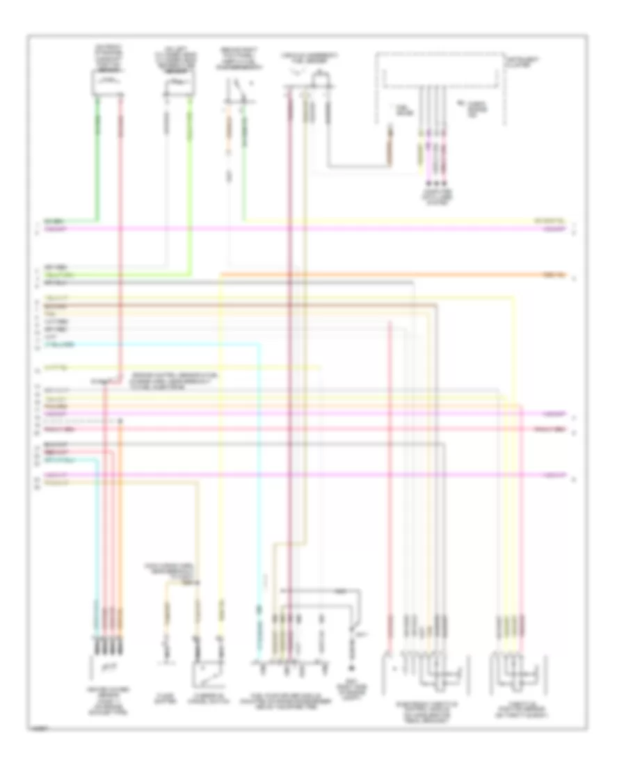
4.6L, Engine Performance Wiring Diagram (2 of 6) for Ford Pickup F150 2004
List of elements for 4.6L, Engine Performance Wiring Diagram (2 of 6) for Ford Pickup F150 2004:
- (cop) 1 cntl
- (cop) 2 cntl
- (cop) 3 cntl
- (cop) 4 cntl
- (cop) 5 cntl
- (cop) 6 cntl
- (cop) 7 cntl
- (cop) 8 cntl
- (engine control sensor & fuel charge harn, near breakout to cop 4) s170
- (engine control sensor & fuel charge harn, near breakout to fuel inj 3)
- (engine control sensor & fuel charge harn, near breakout to egr system module)
- (on left rear of engine) knock sensor
- (on lower front of engine) crankshaft position sensor
- (right rear of engine compt)
- (right rear of engine compt) powertrain control module (pcm)
- (top left side of engine) ignition transformer capacitor 2
- (top right side of engine) ignition transformer capacitor 1
- C175e
- Coil on plug
- Dpfe
- Electronic throttle control motor (on throttle body)
- Etc mtr+/-
- Four-wheel drive switch
- Frpt sen sig
- Fuel rail pressure transducer sensor (on top left side of engine)
- G103
- Ho2s 11
- Ho2s 21
- Nca
- Power steering pressure sensor (on front of engine)
- Psp sens
- Red
- S136 (engine control sensor & fuel charge harn, near breakout to cop 8)
- S161
- S162
- S199
- Tan
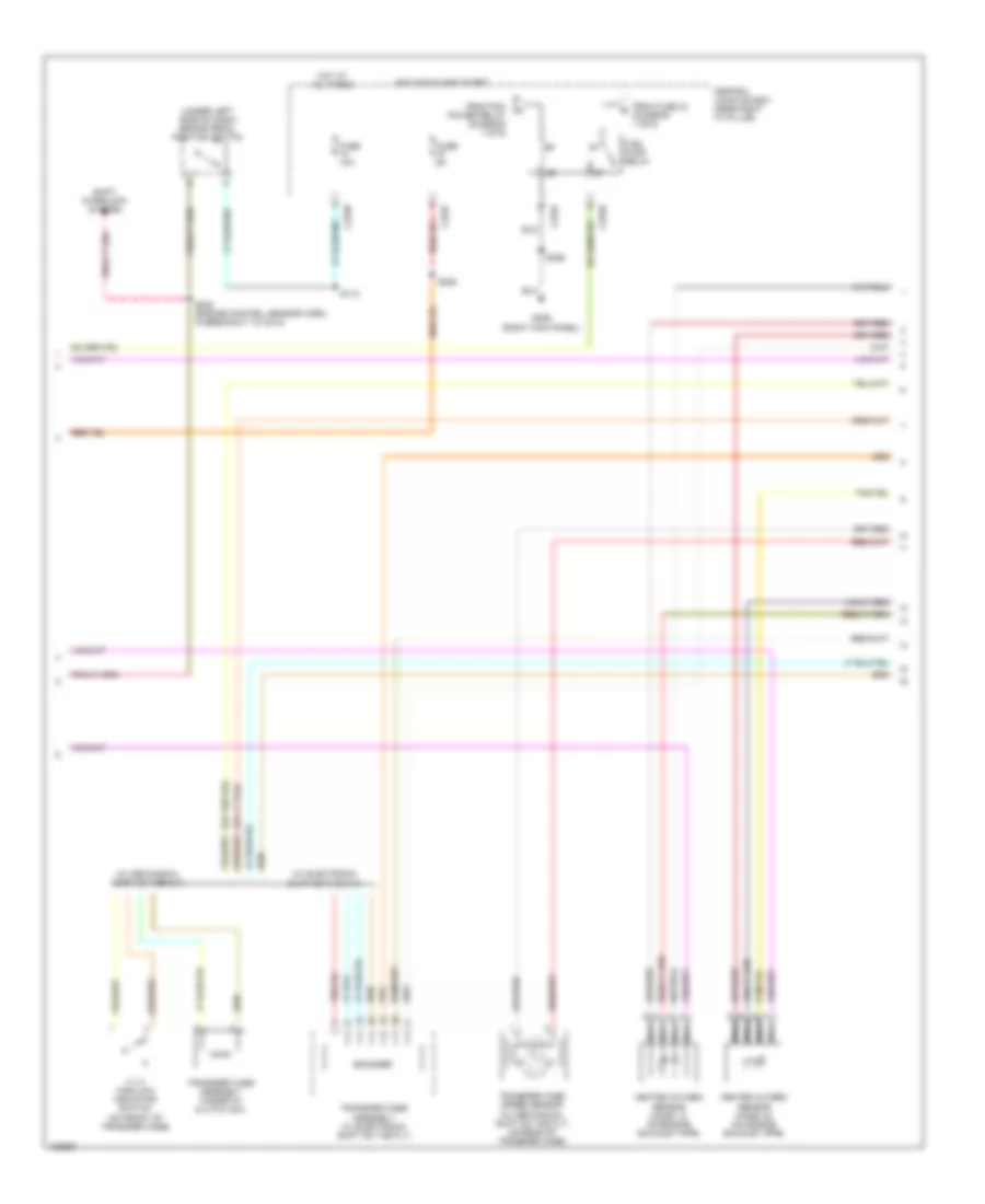
4.6L, Engine Performance Wiring Diagram (3 of 6) for Ford Pickup F150 2004
List of elements for 4.6L, Engine Performance Wiring Diagram (3 of 6) for Ford Pickup F150 2004:
- (engine control sensor & fuel charge harn, near breakout to cop 3
- (engine control sensor & fuel charge harn, near breakout to fuel inj 8)
- (engine control sensor & fuel charge harn, near breakout to ho2s 11)
- (left side of engine compt) auxiliary relay box 1
- (right rear of engine compt) powertrain control module
- (top left side of engine) egr system module
- C175e
- Clockwise motor 4 x 4 relay
- Cmp sen
- Counter- clockwise motor 4 x 4 relay
- Crk sens +
- Crk sens -
- Dpfe
- Etc mtr +/-
- Evap can vv
- Evap canister vent valve (left rear of engine compt)
- Evr
- Fuel inj 1
- Fuel inj 2
- Fuel inj 3
- Fuel inj 4
- Fuel inj 5
- Fuel inj 6
- Fuel inj 7
- Fuel inj 8
- Fuel injectors
- Head tmp sen
- Heated oxygen sensor (ho2s) 21 (on engine exhaust pipe)
- Ho2s 11 htr
- Ho2s 21 htr
- Imtv cntl
- Intake manifold tuning valve (on top left side of engine)
- Knk sen1 +
- Knk sen1 -
- Map
- Nca
- Red
- Ref voltage
- S129
- S131
- S154
- Sig return
- Sig rtn
- Tan
- Tan/red
- Tps ref vlt
- Tps sig 1
- Tps sig 2
- Tps sig rtn
- Vref
4.6L, Engine Performance Wiring Diagram (4 of 6) for Ford Pickup F150 2004
List of elements for 4.6L, Engine Performance Wiring Diagram (4 of 6) for Ford Pickup F150 2004:
- charge harn, near breakout
- (behind right kick panel) inertia fuel shut-off switch
- (engine control sensor & fuel
- (main wiring harn, near breakout to c3007) s284
- (on front of engine) camshaft position sensor
- (on left cylinder head) cylinder head temperature sensor
- (vehicle underbody) fuel sender
- Check engine ind
- Computer data lines system
- Electronic throttle control module (on accelerator pedal bracket)
- Floor shifter
- Fpm
- Fuel gauge
- Fuel pump driver module (mounted on frame crossmember above the spare tire)
- G401 (right side of engine compt)
- Gnd
- Heated oxygen sensor (ho2s) 11 (on engine exhaust pipe)
- Instrument cluster
- Nca
- Overdrive cancel switch
- Pwr
- S135
- S411
- Tan
- Throttle position sensor (on throttle body)
- To fuel injector #8
4.6L, Engine Performance Wiring Diagram (5 of 6) for Ford Pickup F150 2004
List of elements for 4.6L, Engine Performance Wiring Diagram (5 of 6) for Ford Pickup F150 2004:
- (under left side of dash) brake pedal position switch
- (w/ electronic shift on the fly)
- (w/ mechanical shift on the fly)
- 4 x 4 high/low indicator switch (on front of transfer case)
- C270f
- Central junction box (near right "a" pillar)
- Encoder
- From fuse 34 (diagram 1 of 6)
- From pcm power relay (diagram 1 of 6)
- Fuel pump relay
- Fuse 10a
- Fuse 5a
- G206 (right kick panel)
- Heated oxygen sensor (ho2s) 12 (on engine exhaust pipe)
- Heated oxygen sensor (ho2s) 22 (on engine exhaust pipe)
- Hot at all times
- Hot in run and start
- Nca
- S112
- S222 (engine control sensor harn, in breakout to c214)
- S225
- S355
- Shift interlock system
- Transfer case assembly (w/ electronic shift on the fly)
- Transfer case assembly magnetic clutch coil
- Transfer case speed sensor (w/ mechanical shift on the fly) (on rear of transfer case)
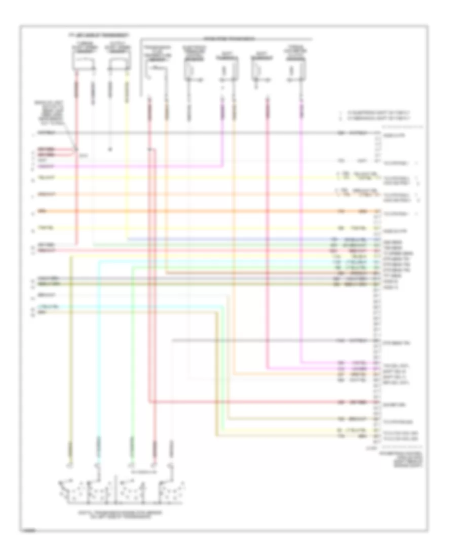
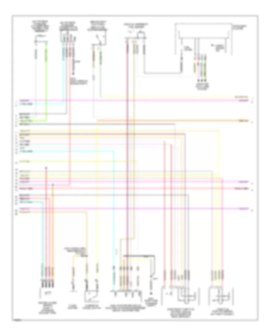
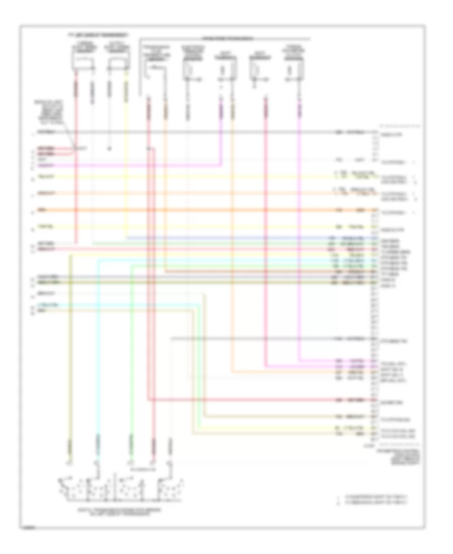
4.6L, Engine Performance Wiring Diagram (6 of 6) for Ford Pickup F150 2004
List of elements for 4.6L, Engine Performance Wiring Diagram (6 of 6) for Ford Pickup F150 2004:
- (762
- (763
- (back-up light switch to rear lamp feed harn, near break- out to pcm
- (on left side of transmission)
- 4r70e/4r75e transmission
- 4wd ind pos 1
- 4wd ind pos 3
- C175t
- Digital transmission range (dtr) sensor (on left side of transmission)
- Dtr sens tr1
- Dtr sens tr2
- Dtr sens tr3
- Dtr sens tr4
- Electronic pressure control solenoid
- Epc sol cntl
- Ho2s 12
- Ho2s 2 htr
- Ho2s 22
- Ho2s 22 htr
- Oss sens
- Output shaft speed sensor
- Powertrain control module (pcm) (right rear of engine compt)
- R n
- S141
- Shift sol a
- Shift sol b
- Shift solenoid a
- Shift solenoid b
- Sig return
- Tc cltch coil sig
- Tc mtr pos 1
- Tc mtr pos 2
- Tc mtr pos sig
- Tc speed sens
- Tcc sol cntl
- Tft sens
- Torque converter clutch solenoid
- Transmission fluid temperature sensor
- Tss sens
- Turbine shaft speed sensor
- W/ electronic shift on the fly
- W/ mechanical shift on the fly
5.4L
5.4L, Engine Performance Wiring Diagram (1 of 6) for Ford Pickup F150 2004
List of elements for 5.4L, Engine Performance Wiring Diagram (1 of 6) for Ford Pickup F150 2004:
- (ccw) 4 x 4 relay
- (cw) 4 x 4 relay
- (engine control sensor harn, near
- (engine control sensor harn, near breakout to c139)
- (engine control sensor harn, near breakout to g102) s106
- (near center of dash)
- (right rear of engine compt) g102
- (right rear of engine compt) g103
- 4 x 4 center axle disconnect solenoid (on right side of engine compt)
- 4 x 4 sol cntl
- 4wd sw
- A/c cltch prs sw
- A/c cltch rly
- A/c system
- Abs control module breakout)
- Airbag dep sig
- Anti-theft on ind
- Anti-theft system
- Apps sig 1
- Apps sig 2
- Apps sig 3
- Audio unit
- Aux spd cntl
- Battery
- Brk ped pos sw
- C125
- C175b
- C270a red
- C270f
- C270g red
- C290a
- Can bus +
- Can bus -
- Central junction box (near right "a" pillar)
- Computer data lines system
- Control system
- Cruise
- Cruise control system
- Data link connector
- Deactivator sw
- Etc module
- Evap can vnt vlv
- Evap canister vent control solenoid (vehicle underbody)
- Feps
- Ftpt sens
- Ftpt sens sig
- Fuel pmp drv mod
- Fuel tank pressure transducer sensor (at fuel tank)
- Fuse 15a
- Fuse 20a
- Fuse 30a
- Fuse 5a
- Fuse 7.5a
- Generator com
- Generator mon
- Ground
- Hot at all times
- Hot in run or start
- Iat sens sig
- Maf sens sig
- Mass airflow/ intake air temp- erature sensor (on top of engine)
- O/d cancel sw
- Panel) g206
- Pcm power diode
- Pcm power relay
- Pcm pwr relay
- Power
- Powertrain control module (pcm) (right rear of engine compt)
- Red
- Red/pnk
- Rx sig
- S102
- S103
- S104
- S105
- S107
- S117
- S118
- S140
- S199
- S355
- Sig rtn
- Start relay
- Starting/charging system
- Tan
- To fuel pump relay (diagram 5 of 6)
- Tx sig
- Vss
- Windshield wiper motor (left rear of engine compt)
5.4L, Engine Performance Wiring Diagram (2 of 6) for Ford Pickup F150 2004
List of elements for 5.4L, Engine Performance Wiring Diagram (2 of 6) for Ford Pickup F150 2004:
- (cop) 1 cntl
- (cop) 2 cntl
- (cop) 3 cntl
- (cop) 4 cntl
- (cop) 5 cntl
- (cop) 6 cntl
- (cop) 7 cntl
- (cop) 8 cntl
- (engine control sensor & fuel charge harn, near breakout to cop 4) s170
- (engine control sensor & fuel charge harn, near breakout to cop 8)
- (engine control sensor & fuel charge harn, near breakout to egr system module)
- (lower right rear of engine) engine oil temperature sensor
- (near crankshaft pulley) crankshaft position sensor
- (on top left rear of engine)
- (on top right rear of engine) knock sensor 1
- (right rear of engine compt)
- (right rear of engine compt) powertrain control module (pcm)
- (top left side of engine) ignition transformer capacitor 2
- (top right side of engine) ignition transformer capacitor 1
- C175e
- Coil on plug
- Electronic throttle control motor (on throttle body)
- Eot sens
- Etc mtr+/-
- Four-wheel drive switch
- Frpt sen sig
- Fuel rail pressure transducer sensor (on top left side of engine)
- G103
- Ho2s 11
- Ho2s 21
- Knk sen 2 +
- Knk sen 2 -
- Knock sensor 2
- Nca
- Power steering pressure sensor (on front of engine)
- Psp sens
- Red
- S136 (engine control sensor & fuel charge harn, near break- to cop 8)
- S161
- S162
- S199
- Tan
5.4L, Engine Performance Wiring Diagram (3 of 6) for Ford Pickup F150 2004
List of elements for 5.4L, Engine Performance Wiring Diagram (3 of 6) for Ford Pickup F150 2004:
- (engine control sensor & fuel charge harn, near breakout to cop 3
- (engine control sensor & fuel charge harn, near breakout to fuel inj 8)
- (engine control sensor & fuel charge harn, near breakout to fuel inj 8)
- (engine control sensor & fuel charge harn, near breakout to ho2s 11)
- (left side of engine compt) auxiliary relay box 1
- (on front of left cylinder head) camshaft position sensor 2
- (on front of right cylinder head) camshaft position sensor 1
- (right rear of engine compt) powertrain control module
- C175e
- Clockwise motor 4 x 4 relay
- Cmcv mon
- Cmp sen 1
- Cmp sen 2
- Counter- clockwise motor 4 x 4 relay
- Crk sens +
- Crk sens -
- Etc mtr +/-
- Evap can vv
- Evap canister vent valve (left rear of engine compt)
- Fuel inj 1
- Fuel inj 2
- Fuel inj 3
- Fuel inj 4
- Fuel inj 5
- Fuel inj 6
- Fuel inj 7
- Fuel inj 8
- Fuel injectors
- Head tmp sen
- Heated oxygen sensor (ho2s) 21 (on engine exhaust pipe)
- Ho2s 11 htr
- Ho2s 21 htr
- Knk sen1 +
- Knk sen1 -
- Nca
- Red
- Ref voltage
- S129
- S131
- S135
- S154
- Sig return
- Tan
- Tan/red
- Tps ref vlt
- Tps sig 1
- Tps sig 2
- Tps sig rtn
- Variable timing valve 1 (top right front of engine)
- Variable timing valve 2 (top left front of engine)
- Vct vlv 1
- Vct vlv 2
5.4L, Engine Performance Wiring Diagram (4 of 6) for Ford Pickup F150 2004
List of elements for 5.4L, Engine Performance Wiring Diagram (4 of 6) for Ford Pickup F150 2004:
- (behind right kick panel)
- (main wiring harn, near breakout to c3007) s284
- (on top rear of engine) charge motion control valve
- (on top rear of engine) cylinder head temperature sensor
- (vehicle underbody) fuel sender
- Check engine ind
- Cmcvc
- Cmcvcm
- Computer data lines system
- Electronic throttle control module (on accelerator pedal bracket)
- Floor shifter
- Fpm
- Fuel gauge
- Fuel pump driver module (mounted on frame crossmember above the spare tire)
- G103 (right rear of engine compt)
- G401 (right side of engine compt)
- Gnd
- Heated oxygen sensor (ho2s) 11 (on engine exhaust pipe)
- Inertia fuel shut-off switch
- Instrument cluster
- Nca
- Overdrive cancel switch
- Pwr
- S411
- Tan
- Throttle position sensor (on throttle body)
- Vpwr
5.4L, Engine Performance Wiring Diagram (5 of 6) for Ford Pickup F150 2004
List of elements for 5.4L, Engine Performance Wiring Diagram (5 of 6) for Ford Pickup F150 2004:
- (right kick panel)
- (w/ electronic shift on the fly)
- (w/ mechanical shift on the fly)
- 4 x 4 high/low indicator switch (on front of transfer case)
- Brake pedal position switch
- C270f
- Central junction box (near right "a" pillar)
- Encoder
- From fuse 34 (diagram 1 of 6)
- From pcm power relay (diagram 1 of 6)
- Fuel pump relay
- Fuse 10a
- Fuse 5a
- G206
- Heated oxygen sensor (ho2s) 12 (on engine exhaust pipe)
- Heated oxygen sensor (ho2s) 22 (on engine exhaust pipe)
- Hot at all times
- Hot in run and start
- Nca
- S112
- S222 (engine control sensor harn, in breakout to c214)
- S225
- S355
- Shift interlock system
- Transfer case assembly (w/ electronic shift on the fly)
- Transfer case assembly magnetic clutch coil
- Transfer case speed sensor (w/ mechanical shift on the fly) (on rear of transfer case)
5.4L, Engine Performance Wiring Diagram (6 of 6) for Ford Pickup F150 2004
List of elements for 5.4L, Engine Performance Wiring Diagram (6 of 6) for Ford Pickup F150 2004:
- (762
- (763
- (back-up light switch to rear lamp feed harn, near break- out to pcm
- (on left side of transmission)
- 4r70e/4r75e transmission
- 4wd ind pos 1
- 4wd ind pos 3
- C175t
- Digital transmission range (dtr) sensor (on left side of transmission)
- Dtr sens tr1
- Dtr sens tr2
- Dtr sens tr3
- Dtr sens tr4
- Electronic pressure control solenoid
- Epc sol cntl
- Ho2s 12
- Ho2s 2 htr
- Ho2s 22
- Ho2s 22 htr
- Oss sens
- Output shaft speed sensor
- Powertrain control module (pcm) (right rear of engine compt)
- R n
- S141
- Shift sol a
- Shift sol b
- Shift solenoid a
- Shift solenoid b
- Sig return
- Tc cltch coil sig
- Tc mtr pos 1
- Tc mtr pos 2
- Tc mtr pos sig
- Tc speed sens
- Tcc sol cntl
- Tft sens
- Torque converter clutch solenoid
- Transmission fluid temperature sensor
- Tss sens
- Turbine shaft speed sensor
- W/ electronic shift on the fly
- W/ mechanical shift on the fly

 Čeština
 Dansk
Dansk Deutsch
 Ελληνικά
 English
 Español
 Suomi
Suomi Français
 Français
 עברית
עברית Hrvatski
 Magyar
 Italiano
 日本語
日本語 한국어
한국어 Nederlands
 Polski
 Português
 Português
 Română
 Русский
 Slovenčina
 Slovenščina
 Svenska
 Türkçe
 中文 (中国)