ENGINE PERFORMANCE
1.5L
1.5L, Engine Controls Wiring Diagram (1 of 5) for Honda CR-Z EX 2014
 https://portal-diagnostov.com/license.html
Automotive Electricians Portal FZCO
Automotive Electricians Portal FZCO
https://portal-diagnostov.com/license.html
https://portal-diagnostov.com/license.html
Automotive Electricians Portal FZCO
Automotive Electricians Portal FZCO
List of elements for 1.5L, Engine Controls Wiring Diagram (1 of 5) for Honda CR-Z EX 2014:
- (left end of dash) g501
- (lower front of engine compt) ect sensor 2
- (right front of engine compt) a/c pressure sensor
- (under left rear of vehicle) evap canister vent shut valve
- A/f sensor relay
- A10
- A11
- A12
- A13
- A14
- A15
- A16
- A17
- A18
- A19
- A20
- A21
- A22
- A23
- A24
- A25
- A26
- A27
- A28
- A29
- A30
- A31
- A32
- A33
- A34
- A35
- A36
- A37
- A38
- A39
- A40
- A41
- A42
- A43
- A44
- A45
- A46
- A47
- A48
- A49
- Air conditioning system
- App sensor (left side of dash)
- B10
- B18
- B25
- Brake booster pressure sensor a (on brake booster assembly)
- Brake booster pressure sensor b (on brake booster assembly)
- C105
- C116
- C118
- C305
- Clutch pedal position switch b (m/t)
- Computer data lines system
- Cvt
- Eld unit
- Electronic power steering system
- Ftp sensor (in fuel tank unit)
- Fuse 10a
- Fuse 7.5a
- G403 (left side of dash)
- Hot at all times
- Hot in on or start
- J/c c006
- Park pin switch/ shift lock solenoid/ a/t gear position indicator panel light (cvt) (park pin switch: under center console) (shift lock solenoid: base of a/t shift lever)
- Pcm (left side of engine compt)
- Pnk
- Red
- Sound & navigation systems
- Starting/charging system
- Under-dash fuse/relay box (left end of dash)
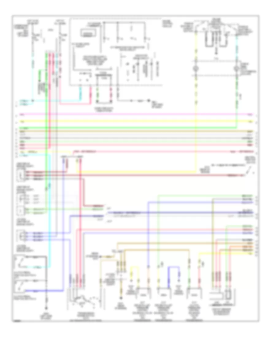
1.5L, Engine Controls Wiring Diagram (2 of 5) for Honda CR-Z EX 2014
List of elements for 1.5L, Engine Controls Wiring Diagram (2 of 5) for Honda CR-Z EX 2014:
- (center of engine compt) j/c c004
- (center of engine compt) j/c c005
- (rear of engine) g101
- 10v stabilizing circuit
- A/t dimming circuit
- A/t gear position indicator drive circuit
- B14
- B17
- C116
- C301
- C305
- Cable reel (cvt) (in steering column)
- Clutch pedal position switch a
- Clutch pedal position switch c (m/t)
- Computer data lines system
- Cruise control combination switch
- Cvt
- Cvt clutch pressure control solenoid valve (on transmission)
- Cvt drive pulley pressure control solenoid valve (cvt) (on transmission)
- Cvt driven pulley pressure control solenoid valve (cvt) (on transmission)
- D18
- Dimming circuit
- Exterior
- F-can transceiver
- Fuse 15a
- Fuse 7.5a
- Fwd
- G101 (rear of engine)
- G151 (in trans- mission)
- G403 (left side of dash)
- G501 (left end of dash)
- Gauge control module
- Hot at all times
- Hot in on or start
- Iat sensor
- Indicator drive circuit
- J/c c004 (center of engine compt)
- J/c c005 (center of engine compt)
- J/c c005 (cvt) (center of engine compt)
- Lights system
- Low fuel ind
- Low oil pressure ind
- M/t
- Maf sensor
- Maf/iat sensor (on engine air intake duct)
- Micu
- Mil ind
- Neutral position switch
- Paddle shifter (+) (upshift switch)
- Paddle shifter (-) (downshift switch)
- Pnk
- Red
- T10
- Transmission range switch (cvt) (on transmission housing)
- Under-dash fuse/relay box (left end of dash)
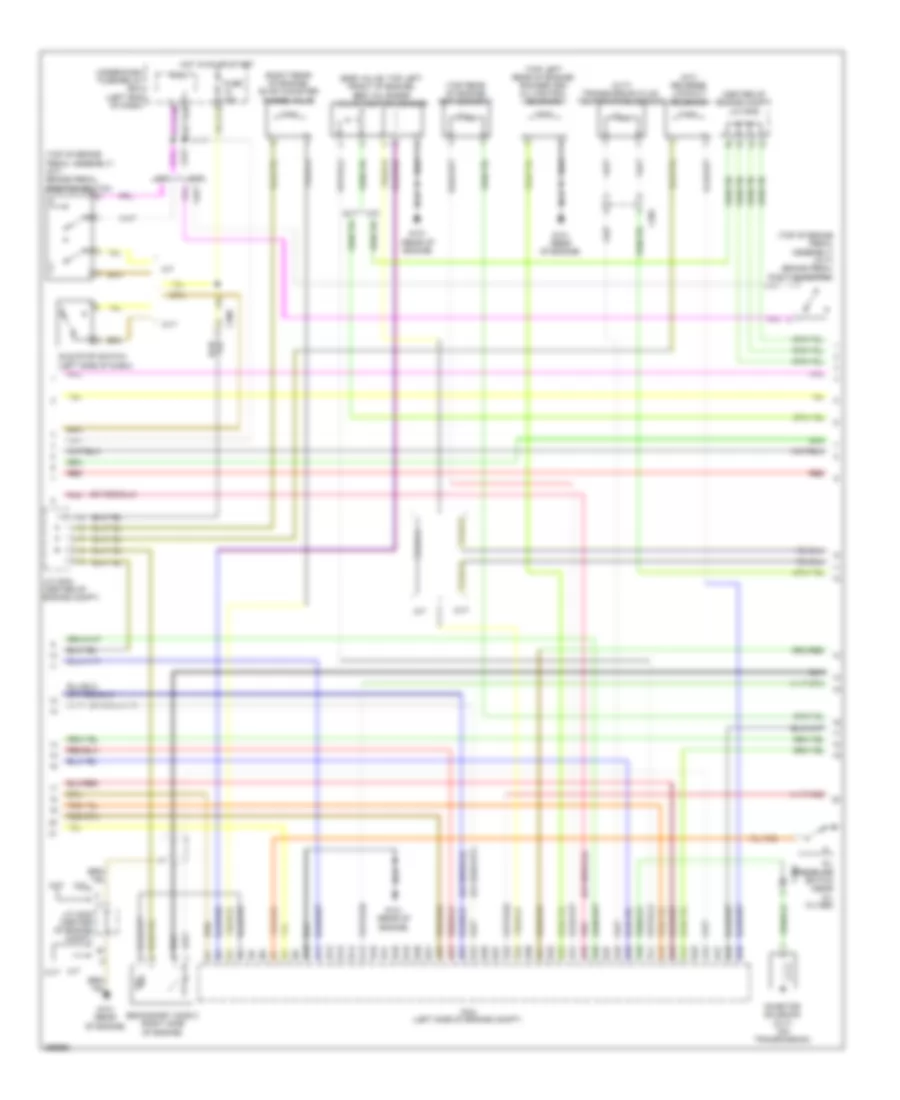
1.5L, Engine Controls Wiring Diagram (3 of 5) for Honda CR-Z EX 2014
List of elements for 1.5L, Engine Controls Wiring Diagram (3 of 5) for Honda CR-Z EX 2014:
- (center of engine compt) j/c c005
- (cvt) transmission fluid temperature sensor
- (egr valve: top left front of engine) egr valve/egr valve position sensor
- (m/t) reverse lockout solenoid
- (right rear of engine) evap canister purge valve
- (top left rear of engine) rocker arm oil control solenoid
- (top of brake pedal assembly) (cvt) brake pedal position switch
- (top of brake pedal assembly) (m/t) brake pedal position switch
- (top rear of engine) ect sensor 1
- B10
- B11
- B12
- B13
- B14
- B15
- B16
- B17
- B18
- B19
- B20
- B21
- B22
- B23
- B24
- B25
- B26
- B27
- B28
- B29
- B30
- B31
- B32
- B33
- B34
- B35
- B36
- B37
- B38
- B39
- B40
- B41
- B42
- B43
- B44
- B45
- B46
- B47
- B48
- B49
- C301
- C305
- Cvt
- Fuse 10a
- G101 (rear of engine)
- Hot in 0n or start
- Idle stop switch (left side of dash)
- Inhibitor solenoid (cvt) (on transmission)
- J/c c004 (center of engine compt)
- J/c c005 (center of engine compt)
- M/t
- Micu
- Oil pressure switch (near oil filter)
- Pcm (left side of engine compt)
- Pnk
- Red
- Secondary ho2s 2 (right side of engine)
- Under-dash fuse/relay box (left end of dash)
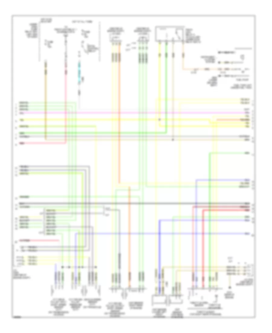
1.5L, Engine Controls Wiring Diagram (4 of 5) for Honda CR-Z EX 2014
List of elements for 1.5L, Engine Controls Wiring Diagram (4 of 5) for Honda CR-Z EX 2014:
- (center of engine compt) j/c c004
- (center of engine compt) j/c c005
- (on transmission housing)
- B11
- B19
- B21
- C116
- C118
- C304
- C305
- Ckp sensor (lower left front of engine)
- Cmp sensor (top rear of engine)
- Cvt
- Cvt drive pulley input shaft speed sensor (cvt)
- Cvt driven pulley output shaft speed sensor (on transmission housing)
- Cvt driven pulley pressure sensor (cvt)
- Etcs control relay
- Fuel pump
- Fuel tank unit (inside fuel tank)
- Fuse 15a
- G101 (rear of engine)
- G602 (under driver's seat)
- Hot at all times
- Hot in on or start
- Instrument cluster system
- J/c c005 (center of engine compt)
- M/t
- Map sensor (right rear of engine)
- Pgm-fi main relay 2 (in auxiliary under-hood relay box a)
- Red
- Throttle actuator
- Throttle body (top right rear of engine)
- Throttle open sensor
- To pgm-fi main relay 1 (diagram 5 of 5)
- Under- dash fuse/ relay box (left end of dash)
- Vehicle speed sensor (cvt) (on transaxle)
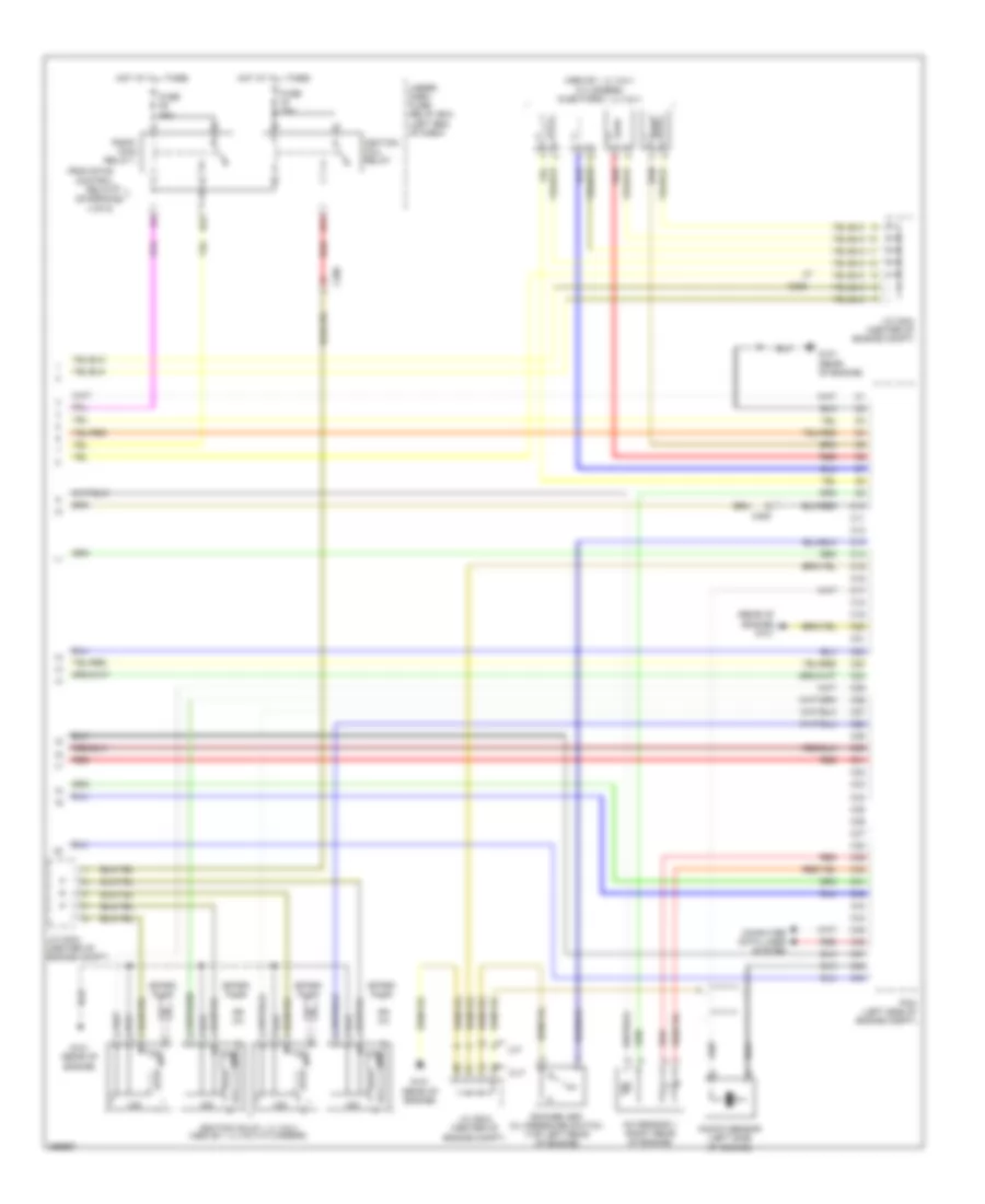
1.5L, Engine Controls Wiring Diagram (5 of 5) for Honda CR-Z EX 2014
List of elements for 1.5L, Engine Controls Wiring Diagram (5 of 5) for Honda CR-Z EX 2014:
- (above 1, 2, 3 & 4 cylinders) injectors 1, 2, 3 & 4
- (rear of engine) g101
- A/f sensor 1 (right rear of engine)
- B22
- B31
- C10
- C11
- C12
- C13
- C14
- C15
- C16
- C17
- C18
- C19
- C20
- C21
- C22
- C23
- C24
- C25
- C26
- C27
- C28
- C29
- C30
- C305
- C31
- C32
- C33
- C34
- C35
- C36
- C37
- C38
- C39
- C40
- C41
- C42
- C43
- C44
- C45
- C46
- C47
- C48
- C49
- Computer data lines system
- Cvt
- From etcs control relay (diagram a 4 of 5)
- Fuse 15a
- G101 (rear of engine)
- Hot at all times
- Icm
- Ignition coil relay
- Ignition coils 1, 2, 3 & 4 (above 1, 2, 3 & 4 cylinders)
- J/c c004 (center of engine compt)
- J/c c005 (center of engine compt)
- Knock sensor (left side of engine)
- M/t
- Pcm (left side of engine compt)
- Pgm-fi main relay 1
- Red
- Rocker arm oil pressure switch (top left rear of engine)
- Spark plug
- Under- dash fuse/ relay box (left end of dash)
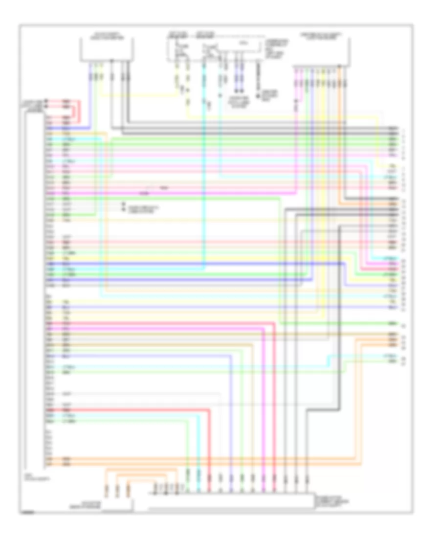
1.5L, IMA Wiring Diagram (1 of 4) for Honda CR-Z EX 2014
List of elements for 1.5L, IMA Wiring Diagram (1 of 4) for Honda CR-Z EX 2014:
- (center of dash) g502
- (center of ima compt) junction board
- (in ima compt) dc-dc converter
- A10
- A11
- A12
- A13
- A14
- A15
- A16
- A17
- A18
- A19
- A20
- A21
- A22
- A23
- A24
- A25
- A26
- A27
- A28
- A29
- A30
- A31
- A32
- B10
- B11
- B12
- B13
- B14
- B15
- B16
- B17
- B18
- B19
- B20
- B21
- B22
- B23
- B24
- B26
- C106
- Computer data lines system
- Fuse 10a
- Fuse 7.5a
- Hot in on or start
- Ima motor (rear of engine)
- Mcm (in ima compt)
- Micu
- Nca
- Phase motor current sensor (in ima compt)
- Pnk
- Red
- T12
- T13
- T14
- Tan
- Under-dash fuse/relay box (left end of dash)
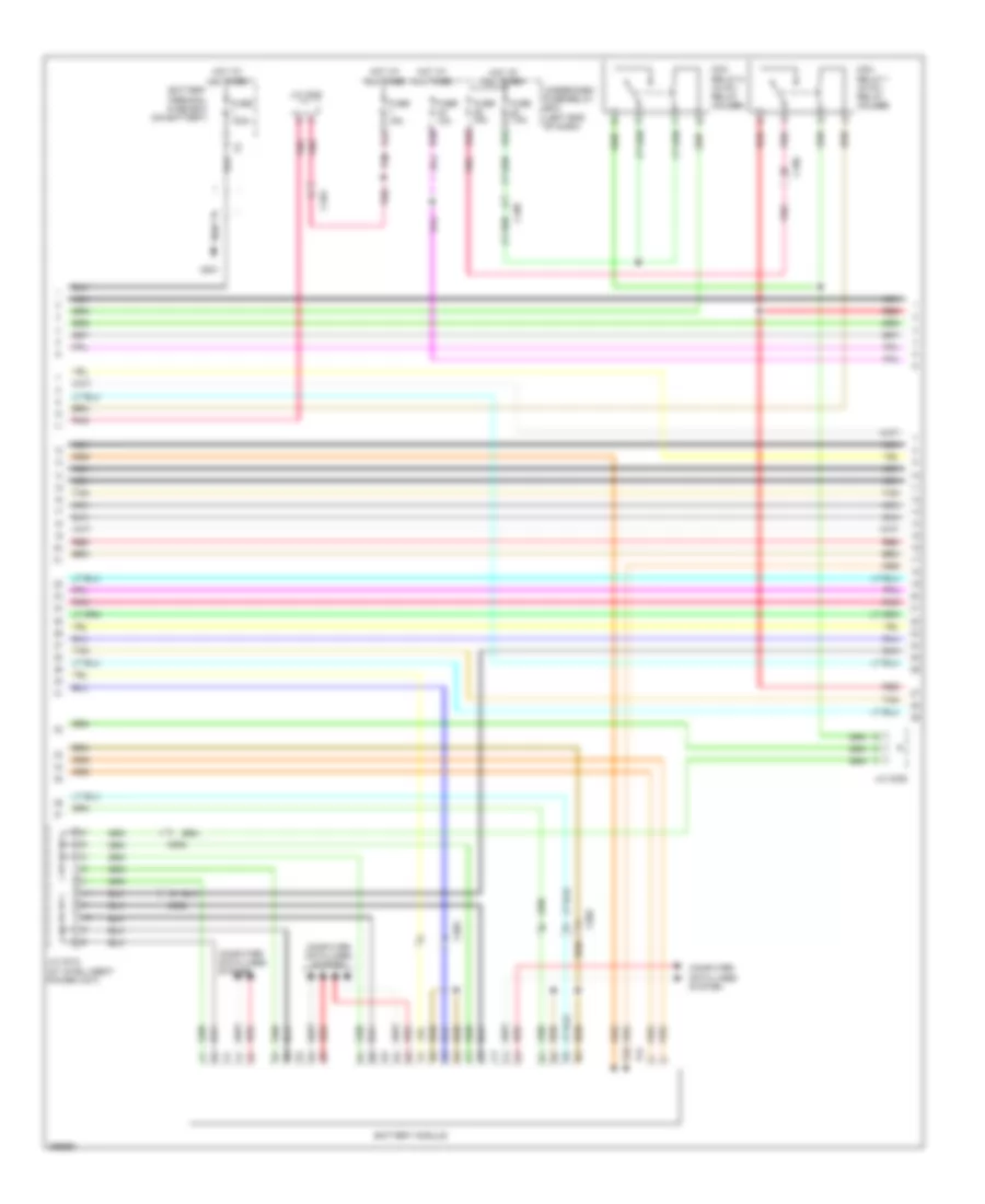
1.5L, IMA Wiring Diagram (2 of 4) for Honda CR-Z EX 2014
List of elements for 1.5L, IMA Wiring Diagram (2 of 4) for Honda CR-Z EX 2014:
- B30
- Battery module
- Battery terminal fuse box (on battery)
- C103
- C106
- C502
- Computer data lines system
- D32
- D42
- D48
- Fuse 100a
- Fuse 10a
- Fuse 15a
- Fuse 7.5a
- G301
- Hot at all times
- J/c c001
- J/c c008
- J/c c010 (at intelligent power unit)
- Mcm relay 1 (in ipu relay holder)
- Mcm relay 2 (in ipu relay holder)
- Nca
- Pnk
- Red
- T21
- T22
- Tan
- Under-dash fuse/relay box (left end of dash)
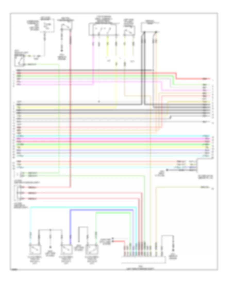
1.5L, IMA Wiring Diagram (3 of 4) for Honda CR-Z EX 2014
List of elements for 1.5L, IMA Wiring Diagram (3 of 4) for Honda CR-Z EX 2014:
- (left side of dash) idle stop switch
- (m/t) backup light switch
- (top of brake pedal assembly) brake pedal position switch
- A13
- A14
- A18
- A23
- A25
- A35
- B10
- B24
- B25
- C106
- C15
- C305
- C45
- C46
- Clutch pedal position switch a (m/t)
- Clutch pedal position switch b (m/t)
- Clutch pedal position switch c (m/t)
- Computer data lines system
- Cvt
- Fuse 10a
- G101 (rear of engine)
- G403 (left side of dash)
- G701 (right "c" pillar)
- Hot in on or start
- Ipu module fan (behind ipu lid)
- J/c c004 (center of engine compt)
- J/c c005 (center of engine compt)
- M/t
- Nca
- Neutral position switch
- Pcm (left side of engine compt)
- Pnk
- Red
- Tan
- Terminal base
- Under-dash fuse/relay box (left end of dash)
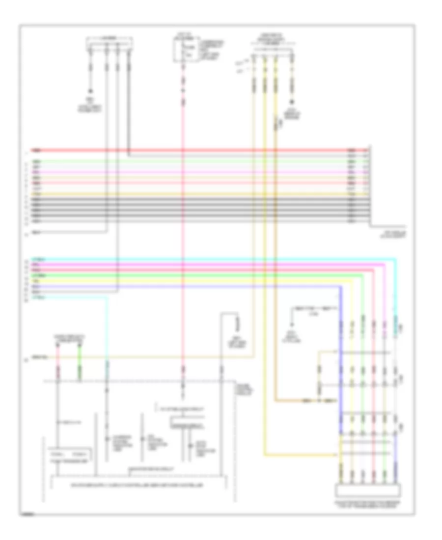
1.5L, IMA Wiring Diagram (4 of 4) for Honda CR-Z EX 2014
List of elements for 1.5L, IMA Wiring Diagram (4 of 4) for Honda CR-Z EX 2014:
- (center of engine compt) j/c c005
- 10v stabilizing circuit
- Auto stop indicator (led)
- C105
- C106
- C305
- C306
- Charging system indicator (led)
- Computer data lines system
- Cvt
- Dimming circuit
- F-can h
- F-can l
- F-can transceiver
- Fuse 15a
- G101 (rear of engine)
- G501 (left end of dash)
- G701 (right "c" pillar)
- G901 (at intelligent power unit)
- Gauge control module
- Hot at all times
- Ima motor rotor position sensor (top of transmission housing)
- Ima system indicator (led)
- Indicator drive circuit
- J/c c008
- M/t
- Mpi module (in ima compt)
- Nca
- Pnk
- Red
- Tan
- Under-dash fuse/relay box (left end of dash)

 Čeština
 Dansk
Dansk Deutsch
 Ελληνικά
 English
 Español
 Suomi
Suomi Français
 Français
 עברית
עברית Hrvatski
 Magyar
 Italiano
 日本語
日本語 한국어
한국어 Nederlands
 Polski
 Português
 Português
 Română
 Русский
 Slovenčina
 Slovenščina
 Svenska
 Türkçe
 中文 (中国)