ENGINE PERFORMANCE
2.4L
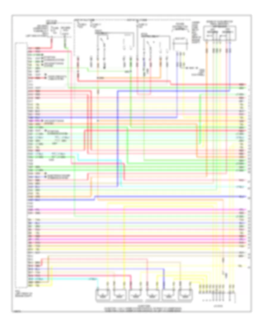
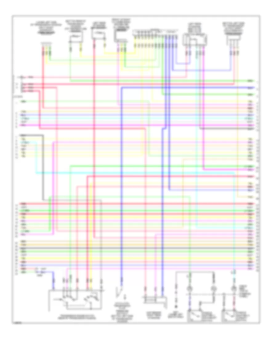
2.4L, Engine Performance Wiring Diagram (1 of 5) for Honda Crosstour EX-L 2014
 https://portal-diagnostov.com/license.html
Automotive Electricians Portal FZCO
Automotive Electricians Portal FZCO
https://portal-diagnostov.com/license.html
https://portal-diagnostov.com/license.html
Automotive Electricians Portal FZCO
Automotive Electricians Portal FZCO
List of elements for 2.4L, Engine Performance Wiring Diagram (1 of 5) for Honda Crosstour EX-L 2014:
- (b12 to b15 not used)
- (left front of engine compt) pcm
- (left kick panel) g302
- (top left rear of engine) g101
- A10
- A11
- A12
- A13
- A14
- A15
- A16
- A17
- A18
- A19
- A20
- A21
- A22
- A23
- A24
- A25
- A26
- A27
- A28
- A29
- A30
- A31
- A32
- A33
- A34
- A35
- A36
- A37
- A38
- A39
- A40
- A41
- A42
- A43
- A44
- A45
- A46
- A47
- A48
- A49
- Air conditioning system
- App sensor (base of accelerator pedal bracket)
- App sensor a
- App sensor b
- B10
- B11
- B16
- B17
- B18
- B19
- B20
- B21
- B22
- B23
- B24
- B25
- B26
- B27
- B28
- B29
- B30
- B31
- C101
- C106
- C306
- Computer data lines system
- Driver's j/b (left side of dash)
- Driver's under-dash fuse/relay box (left end of dash)
- Eld unit
- Etcs control relay
- F15
- Fuse 10 10a
- Fuse 17 15a
- Fuse 18 15a
- G101 (top left rear of engine)
- Hot at all times
- Hot in on or start
- Navigation system
- Oil pressure switch (near oil filter)
- Pgm-fi main relay 1
- Pnk
- Red
- Shift lock solenoid (base of shift lever assembly)
- Starting/ charging system
- To ignition coil relay (diagram 3 of 5)
- Transmission range switch (rear of transmission housing)
- Under-hood fuse/relay box (left rear of engine compt)
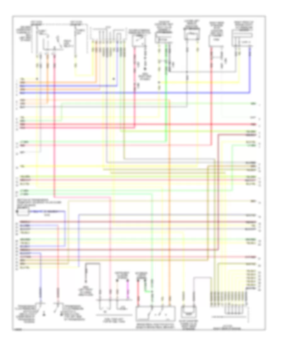
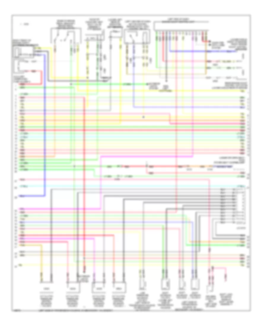
2.4L, Engine Performance Wiring Diagram (2 of 5) for Honda Crosstour EX-L 2014
List of elements for 2.4L, Engine Performance Wiring Diagram (2 of 5) for Honda Crosstour EX-L 2014:
- (bottom of transmission, under shift solenoid valve cover) shift solenoid valve a
- (lower left rear of radiator) ect sensor 2
- (on evap canister vent shut valve assembly) ftp sensor
- (right front of engine compt) a/c pressure sensor
- (right rear of engine) evap canister vent shut valve
- Brake pedal position switch (base of brake pedal bracket)
- C101
- C202
- C304
- C306
- Driver's under-dash fuse/relay box (left end of dash)
- Evap canister purge valve (right rear of engine)
- Exterior lights system
- F12
- F33
- Fuel tank unit (top of fuel tank)
- Fuse 7 15a
- Fuse 9 20a
- G105
- G203 (right end of dash)
- G602 (left front of cargo area floor)
- Hot in on or start
- Instrument cluster system
- J/c c103 (right rear of engine)
- Pgm-fi main relay 2
- Pnk
- Power steering pressure switch (psp)
- Red
- Transmission fluid pressure switch a (2nd clutch) (top left side of transmission)
- Transmission fluid pressure switch b (3rd clutch) (under rear of transmission housing)
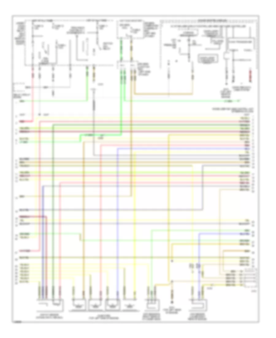
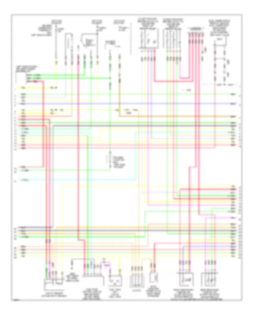
2.4L, Engine Performance Wiring Diagram (3 of 5) for Honda Crosstour EX-L 2014
List of elements for 2.4L, Engine Performance Wiring Diagram (3 of 5) for Honda Crosstour EX-L 2014:
- 5v stabilizer circuit/controller area network controller
- B13
- C101
- C104
- C306
- Ckp sensor (lower right rear of engine)
- Cmp sensor b (right rear of cylinder head)
- Compulsory turning off circuit
- Compulsory turning on circuit
- Computer data lines system
- Driver's junction box (left side of dash)
- Driver's micu
- Driver's under-dash fuse/relay box (left end of dash)
- F-can h
- F-can l
- F-can transceiver
- Fail safe circuit
- From pgm-fi main relay 1 (diagram 1 of 5)
- Fuse 11 15a
- Fuse 12 15a
- Fuse 15 10a
- Fuse 4 7.5a
- Fuse 5 7.5a
- G101 (top left rear of engine)
- Gauge control module
- Hot at all times
- Hot in on or start
- Ignition coil relay
- Immobilizer keyless control unit (steering column)
- Injectors (top left side of engine)
- Low oil pressure ind
- Maf/iat sensor (intake air filter box)
- Mil ind
- Pgm- fi sub relay
- Q16
- Red
- Relay circuit board
- Under- hood fuse/ relay box (left rear of engine compt)
- Warning drive circuit
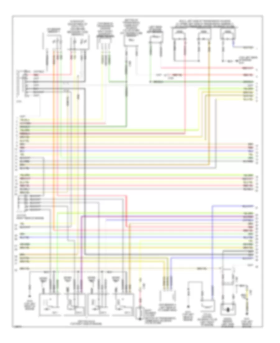
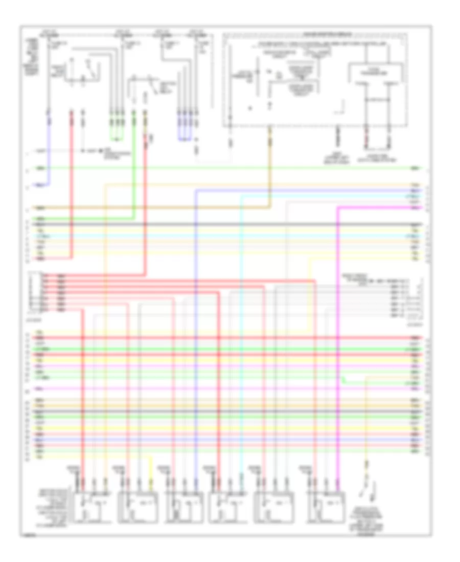
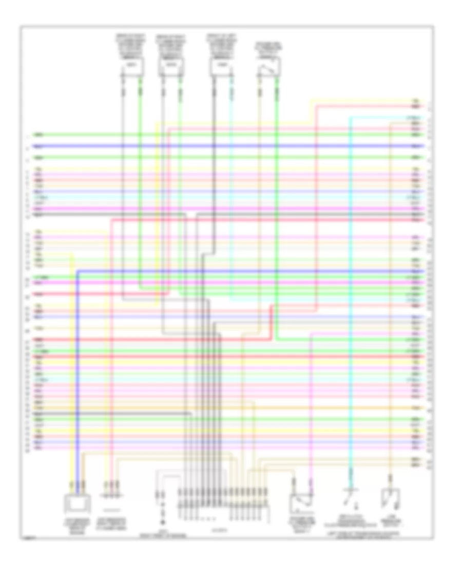
2.4L, Engine Performance Wiring Diagram (4 of 5) for Honda Crosstour EX-L 2014
List of elements for 2.4L, Engine Performance Wiring Diagram (4 of 5) for Honda Crosstour EX-L 2014:
- (b & c: left side of transmission housing) (a: upper left side of transmission assembly) a/t clutch pressure control solenoid valves
- (bottom of transmission, under shift solenoid valve cover) atf temperature sensor
- (in exhaust, downstream of catalytic converter) secondary ho2s (sensor 2)
- (left rear of engine) ect sensor 1
- (top left rear of engine) g101
- (top rear of transmission housing) input shaft (mainshaft) speed sensor
- A/f sensor (sensor 1)
- C101
- C105
- C107
- Cmp sensor a (left rear of cylinder head)
- G101 (top left rear of engine)
- G102 (top left front of engine)
- Icm 1
- Icm 2
- Icm 3
- Icm 4
- Ignition coils (top right side of engine)
- J/c c103 (right rear of engine)
- Knock sensor (left side of engine)
- N/a
- Red
- Shift solenoid valve e (bottom of transmission, under shift solenoid valve cover)
- Spark plug
- Vtc oil control solenoid valve (left front of engine)
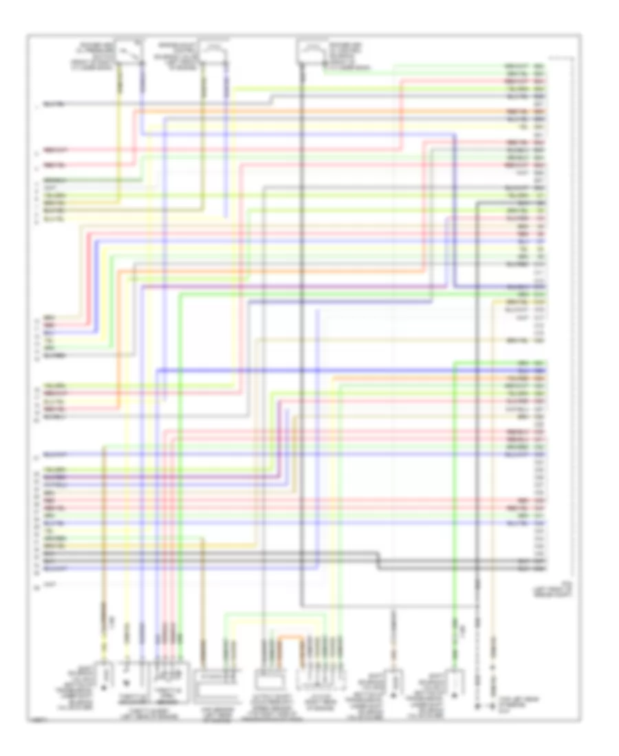
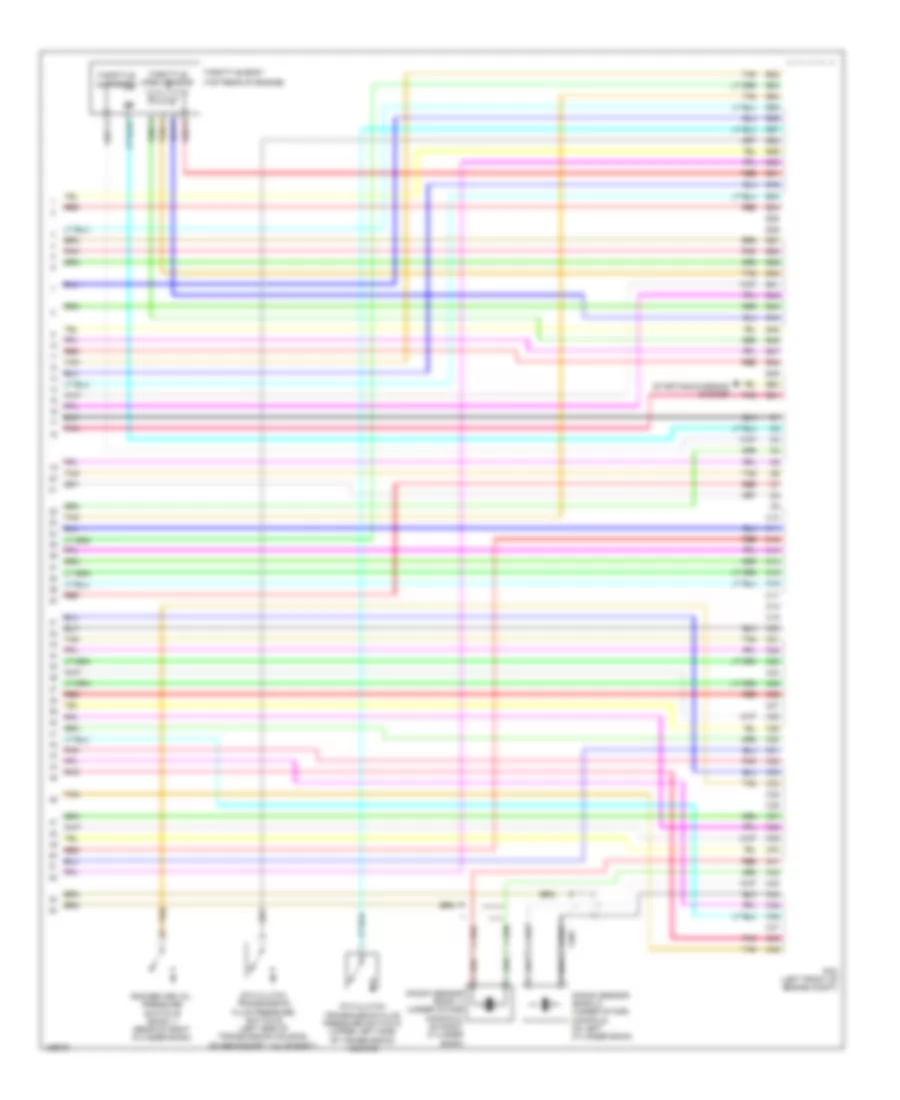
2.4L, Engine Performance Wiring Diagram (5 of 5) for Honda Crosstour EX-L 2014
List of elements for 2.4L, Engine Performance Wiring Diagram (5 of 5) for Honda Crosstour EX-L 2014:
- (bottom of transmission, under shift solenoid valve cover)
- (top left rear of engine) g101
- B32
- B33
- B34
- B35
- B36
- B37
- B38
- B39
- B40
- B41
- B42
- B43
- B44
- B45
- B46
- B47
- B48
- C10
- C105
- C11
- C12
- C13
- C14
- C15
- C16
- C17
- C18
- C19
- C20
- C21
- C22
- C23
- C24
- C25
- C26
- C27
- C28
- C29
- C30
- C31
- C32
- C33
- C34
- C35
- C36
- C37
- C38
- C39
- C40
- C41
- C42
- C43
- C44
- C45
- C46
- C47
- C48
- Engine mount control solenoid valve (left front of engine)
- J/c c103 (right rear of engine)
- Map sensor (left rear of engine)
- Output shaft (countershaft) speed sensor (top right side of transmission housing)
- Pcm (left front of engine compt)
- Red
- Rocker arm oil control solenoid (front of cylinder bank)
- Shift solenoid valve b
- Shift solenoid valve c (bottom of transmission, under shift solenoid valve cover)
- Shift solenoid valve d (bottom of transmission, under shift solenoid valve cover)
- Throttle actuator
- Throttle body (left rear of engine)
- Throttle open sensor
3.5L
3.5L, Engine Performance Wiring Diagram (1 of 7) for Honda Crosstour EX-L 2014
List of elements for 3.5L, Engine Performance Wiring Diagram (1 of 7) for Honda Crosstour EX-L 2014:
- (base of accelerator pedal bracket) app sensor
- (injector 1, 2 & 3: under intake manifold, on right cylinder bank) (injector 4, 5 & 6: under intake manifold, on left cylinder bank)
- A10
- A11
- A12
- A13
- A14
- A15
- A16
- A17
- A18
- A19
- A20
- A21
- A22
- A23
- A24
- A25
- A26
- A27
- A28
- A29
- A30
- A31
- A32
- A33
- A34
- A35
- A36
- A37
- A38
- A39
- A40
- A41
- A42
- A43
- A44
- A45
- A46
- A47
- A48
- A49
- A50
- A51
- Air conditioning system
- App sensor a
- App sensor b
- Atp-p
- B10
- B11
- B12
- B13
- B14
- B15
- B16
- B17
- B18
- B19
- B20
- B21
- C408
- C506
- C507
- Computer data lines system
- Driver's micu
- Driver's under-dash fuse/relay box (left end of dash)
- Eld unit
- Electronic power steering system
- Etcs control relay
- F15
- F23
- Fuse 10a
- Fuse 17 15a
- Fuse 18 15a
- Fuse 8 20a
- G302 (left kick panel)
- Hot at all times
- Hot in on or start
- Injectors
- J/c c016
- Pcm (left front of engine compt)
- Pgm-fi main relay 1
- Pnk
- Power distribution system
- Red
- Starting/ charging system
- Tan
- Under- hood fuse/ relay box (left rear of engine compt)
3.5L, Engine Performance Wiring Diagram (2 of 7) for Honda Crosstour EX-L 2014
List of elements for 3.5L, Engine Performance Wiring Diagram (2 of 7) for Honda Crosstour EX-L 2014:
- (base of brake pedal bracket) brake pedal position switch
- (left center of dash) active control engine mount (acm) control relay
- (left end of dash) engine mount control unit
- (left side of transmission housing, on secondary valve body)
- (lower left rear of radiator) ect sensor 2
- (lower middle front of engine) front engine mount control actuator
- (on evap canister vent shut valve assembly) ftp sensor
- (right front of engine compt) a/c pressure sensor
- (under driver's seat) (4wd) power seat control unit
- 4wd
- A/t clutch pressure control solenoid valve a
- A/t clutch pressure control solenoid valve b
- A/t clutch pressure control solenoid valve c
- A/t clutch pressure control solenoid valve d
- Auxiliary under-dash fuse holder a
- B35
- C142
- C403
- C408
- C412
- C502
- C503
- C507
- C603
- Computer data lines system
- Driver's junction box (left side of dash)
- Exterior lights system
- G302 (left kick panel)
- J/c c015
- Line pressure solenoid valve a (left side of transmission housing, on secondary valve body)
- Pnk
- Rear engine mount control actuator (lower middle rear of engine)
- Red
- Shift lock solenoid (base of shift lever assembly)
- Shift solenoid valve a
- Shift solenoid valve b
- Shift solenoid valve c (lower left side of transmission housing)
- Tan
3.5L, Engine Performance Wiring Diagram (3 of 7) for Honda Crosstour EX-L 2014
List of elements for 3.5L, Engine Performance Wiring Diagram (3 of 7) for Honda Crosstour EX-L 2014:
- (2wd: under middle rear of vehicle) (4wd: under right middle rear of vehicle) evap canister vent shut valve
- (in left exhaust, before catalytic converter) front a/f sensor (b2, s1)
- (in right exhaust, before catalytic converter) rear a/f sensor (b1, s1)
- (left side of dash) keyless access control unit
- 4wd
- B11
- B21
- C18
- C506
- C507
- C603
- C805
- Driver"s micu
- Driver's junction box (left side of dash)
- Driver's under-dash fuse/relay box (left end of dash)
- Evap canister purge valve (right rear of engine)
- F12
- F33
- Front secondary ho2s (b2, s2) (in left exhaust, downstream of catalytic converter)
- Fuel pump control module (behind front of left rear side trim panel)
- Fuel tank unit (top of fuel tank)
- Fuse 11 7.5a
- Fuse 7 15a
- Fuse 9 20a
- G602 (left front of cargo area floor)
- Hot in on or start
- J/c c015
- J/c c016
- Maf/iat sensor (intake air filter box)
- Pgm-fi main relay 2
- Pnk
- Q16
- Rear secondary ho2s (b1, s2) (in right exhaust, downstream of catalytic converter)
- Red
- Tan
3.5L, Engine Performance Wiring Diagram (4 of 7) for Honda Crosstour EX-L 2014
List of elements for 3.5L, Engine Performance Wiring Diagram (4 of 7) for Honda Crosstour EX-L 2014:
- (ignition coils 4 5 & 6: top of left cylinder bank)
- (right front of engine) g101
- 2nd clutch transmission fluid pressure switch a (upper left side of transmission housing)
- Air conditioning system
- C506
- Compulsory turning off circuit
- Compulsory turning on circuit
- Computer data lines system
- F-can h
- F-can l
- F-can transceiver
- Fall safe circuit
- Fuse 11 15a
- Fuse 12 15a
- Fuse 15a
- Fuse 19 20a
- G402 (upper left end of dash)
- Gauge control module
- Hot at all times
- Icm
- Ignition coil relay
- Ignition coils (ignition coils 1 2 & 3: top of right cylinder bank)
- Indicator drive circuit
- J/c c013
- J/c c016
- Low oil pressure ind
- Mil ind
- Nca
- Pgm-fi sub relay
- Red
- Spark plug
- Tan
- Under- hood fuse/ relay box (left rear of engine compt)
3.5L, Engine Performance Wiring Diagram (5 of 7) for Honda Crosstour EX-L 2014
List of elements for 3.5L, Engine Performance Wiring Diagram (5 of 7) for Honda Crosstour EX-L 2014:
- (bottom left side of transmission) output shaft (countershaft) speed sensor
- (bottom rear of transmission housing) atf temperature sensor
- (front of right cylinder bank) rocker arm oil pressure sensor
- (left rear of engine) ect sensor 1
- (left rear of engine) egr valve/ egr valve position sensor
- (lower left side of transmission housing) input shaft (mainshaft) speed sensor
- 4th clutch transmission fluid pressure switch c (bottom left side of transmission housing)
- A17
- A18
- C11
- C12
- C506
- Cable reel (top of steering wheel)
- G401 (under left end of dash)
- J/c c013
- J/c c015
- Map sensor (right rear of engine)
- Paddle shifter (+) (upshift switch)
- Paddle shifter (-) (downshift switch)
- Pnk
- Red
- Tan
- Transmission range switch (rear of transmission housing)
3.5L, Engine Performance Wiring Diagram (6 of 7) for Honda Crosstour EX-L 2014
List of elements for 3.5L, Engine Performance Wiring Diagram (6 of 7) for Honda Crosstour EX-L 2014:
- (front of left cylinder bank) rocker arm oil control solenoid a (bank 2)
- (left side of transmission housing, on secondary valve body)
- (rear of right cylinder bank) rocker arm oil control solenoid a (bank 1)
- (rear of right cylinder bank) rocker arm oil control solenoid b (bank 1)
- 3rd clutch transmission fluid pressure switch b
- Ckp sensor (lower right rear of engine)
- Cmp sensor b (right rear of cylinder head)
- G101 (right front of engine)
- J/c c014
- Line pressure switch
- Pnk
- Red
- Rocker arm oil pressure switch a (bank 1)
- Rocker arm oil pressure switch a (bank 2)
- Tan
3.5L, Engine Performance Wiring Diagram (7 of 7) for Honda Crosstour EX-L 2014
List of elements for 3.5L, Engine Performance Wiring Diagram (7 of 7) for Honda Crosstour EX-L 2014:
- (top rear of engine)
- 5th clutch transmission fluid pressure switch d (upper left side of transmission housing)
- 6th clutch transmission fluid pressure switch e (left side of transmission housing, on secondary valve body)
- B22
- B23
- B24
- B25
- B26
- B27
- B28
- B29
- B30
- B31
- B32
- B33
- B34
- B35
- B36
- B37
- B38
- B39
- B40
- B41
- B42
- B43
- B44
- B45
- B46
- B47
- B48
- B49
- B50
- B51
- C10
- C11
- C12
- C13
- C14
- C15
- C16
- C17
- C18
- C19
- C20
- C21
- C22
- C23
- C24
- C25
- C26
- C27
- C28
- C29
- C30
- C31
- C32
- C33
- C34
- C35
- C36
- C37
- C38
- C39
- C40
- C41
- C42
- C43
- C44
- C45
- C46
- C47
- C48
- C49
- C901
- Knock sensor (bank 1) (under intake manifold, on right cylinder bank)
- Knock sensor (bank 2) (under intake manifold, on left cylinder bank)
- Pcm (left front of engine compt)
- Pnk
- Red
- Rocker arm oil pressure switch b (bank 1) (rear of right cylinder bank)
- Starting/charging system
- Tan
- Throttle actuator
- Throttle body
- Throttle open sensor

 Čeština
 Dansk
Dansk Deutsch
 Ελληνικά
 English
 Español
 Suomi
Suomi Français
 Français
 עברית
עברית Hrvatski
 Magyar
 Italiano
 日本語
日本語 한국어
한국어 Nederlands
 Polski
 Português
 Português
 Română
 Русский
 Slovenčina
 Slovenščina
 Svenska
 Türkçe
 中文 (中国)